Joint of vortex drain tube

A technology for drainage pipes and water pipes, applied in the direction of pipes/pipe joints/fittings, pipes, branch lines, etc., can solve the problems affecting the normal water flow of side inlet pipes, and achieve the effect of stable internal pressure and low drainage noise

Inactive Publication Date: 2011-06-15
禹州市新光铸造有限公司
View PDF6 Cites 2 Cited by
  • Summary
  • Abstract
  • Description
  • Claims
  • Application Information

AI Technical Summary

Problems solved by technology

[0009] The purpose of the present invention is to provide a swirl drain pipe joint to solve the problem of forming a narrower joint between the side water inlet pipe and the vertical pipe in the prior art due to the tangential connection between the side water inlet pipe and the vertical pipe. The technical problem that the water outlet affects the normal water flow of the side inlet pipe

Method used


Image

  • Joint of vortex drain tube
  • Joint of vortex drain tube
  • Joint of vortex drain tube

Examples


Embodiment Construction

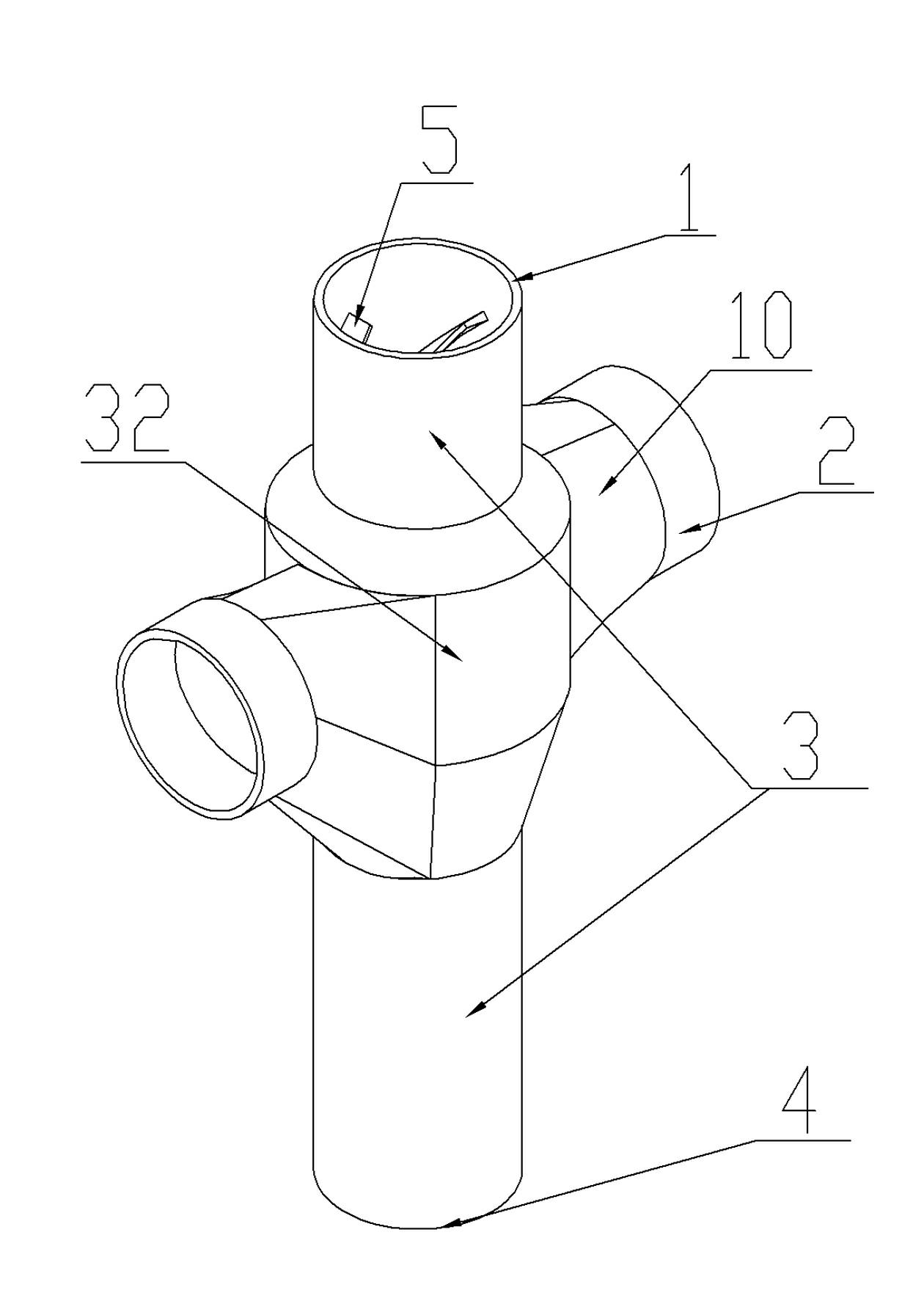
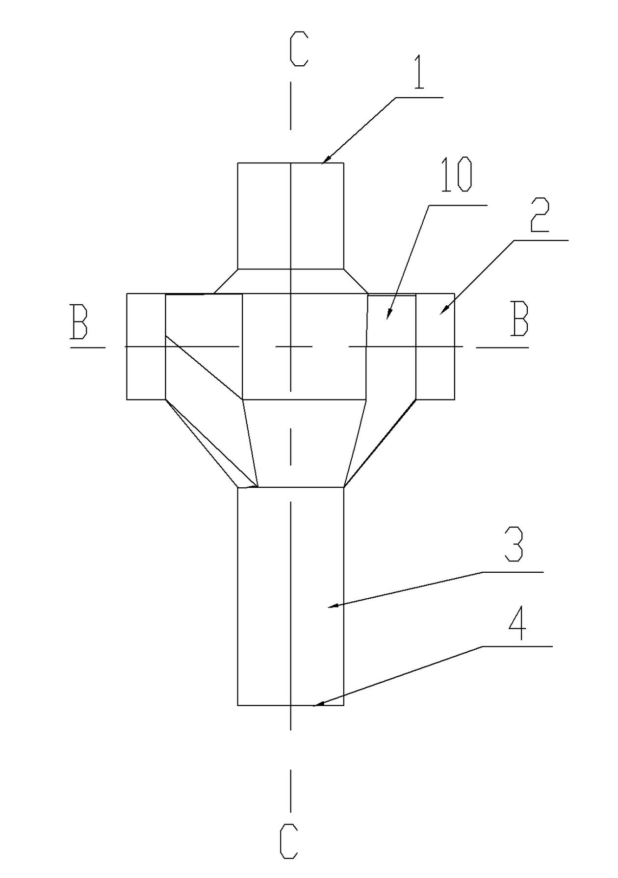
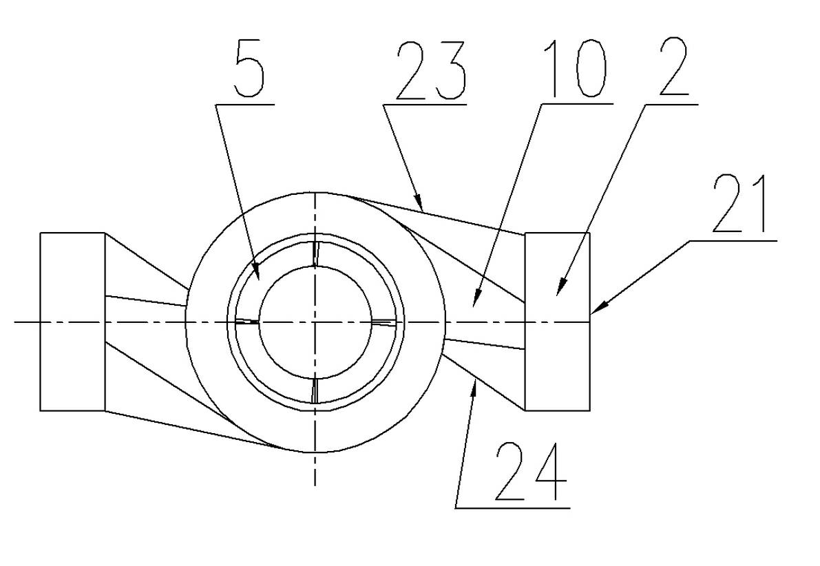
[0036] Such as Figure 1 to Figure 10 As shown, a swirl drain pipe joint includes a vertical pipe 3 and a side water inlet pipe 2 connected to the vertical pipe 3. The upper end of the vertical pipe 3 is correspondingly provided with an upper water inlet 1, and its lower end is correspondingly provided with a water outlet 4. On the inner wall of the standpipe 3, between the upper water inlet 1 and the outlet 4, a spiral guide vane extending axially along the standpipe is provided. In this embodiment, the spiral guide vane includes an upper spiral guide vane 5 and a lower spiral guide vane. The guide vane 6 is provided with two side water inlet pipes 2 on the side of the vertical pipe 3, and the connection part of the side water inlet pipe 2 connected with the vertical pipe 1 is provided with an outlet for connecting the middle cavity of the side water inlet pipe and the vertical pipe. The water inlet 22, the water inlet channel of the side water inlet pipe 2 at the water outle...


PUM


Abstract

The invention discloses a joint of a vortex drain tube, which comprises a vertical tube, wherein an upper water inlet is correspondingly arranged at the upper end of the vertical tube; a drain outlet is correspondingly arranged at the lower end of the vertical tube; spiral guide vanes which axially extend along the vertical tube are arranged between the upper water inlet and the drain outlet on the inner wall of the vertical tube; at least one side water inlet tube is arranged at the side of the vertical tube; a water outlet for communicating the side water inlet tube and a cavity at the middle part of the vertical tube is formed on a connecting part of the vertical tube and the side water inlet tube; a water inlet channel in the position of the water outlet of the side water inlet tube is communicated with the cavity at the middle part of the vertical tube along a tangential line; and the length of a cross section in the position of the water outlet of the connecting part of the side water inlet tube and the vertical tube along the axial direction of the vertical tube is larger than the length of a cross section in the position of the water inlet of the side water inlet tube along the axial direction of the vertical tube.

Description

technical field [0001] The invention belongs to the technical field of building drainage, and in particular relates to a swirling flow drainage pipe joint used for connecting drainage pipes of a single riser drainage system in a building. Background technique [0002] The drainage system of buildings, especially the drainage system of middle and high-rise buildings, is mostly a double riser drainage system, one riser is dedicated to drainage, and the other riser is dedicated to ventilation. This drainage system occupies a large area and consumes a lot of pipe materials. [0003] Ordinary single-standpipe drainage systems are also used, but in ordinary single-standpipe drainage systems, the gas in the pipe is discharged upward while the water is discharged downward, which affects the hydraulic conditions of the drainage. When there is too much water in the pipe, the gas cannot be discharged. Cause problems such as blockage in the pipe, and its drainage condition is not good....

Claims


Application Information

Patent Timeline
Patent Type & Authority Applications(China)
IPC IPC(8): F16L41/02
Inventor 李长庆罗全振李红杰李中灿苏文生刘俊兴陈超
Owner 禹州市新光铸造有限公司
Why Eureka
Try Eureka