Method of measuring gear

A gear measurement and gear technology, applied in the direction of measuring device, measuring circumference, mechanical measuring device, etc., can solve problems such as reduced operability, and achieve the effect of reducing size

Inactive Publication Date: 2011-10-12
MITSUBISHI HEAVY IND LTD
View PDF1 Cites 13 Cited by
  • Summary
  • Abstract
  • Description
  • Claims
  • Application Information

AI Technical Summary

Problems solved by technology

Therefore, operability is reduced

Method used


Image

  • Method of measuring gear
  • Method of measuring gear
  • Method of measuring gear

Examples


Embodiment

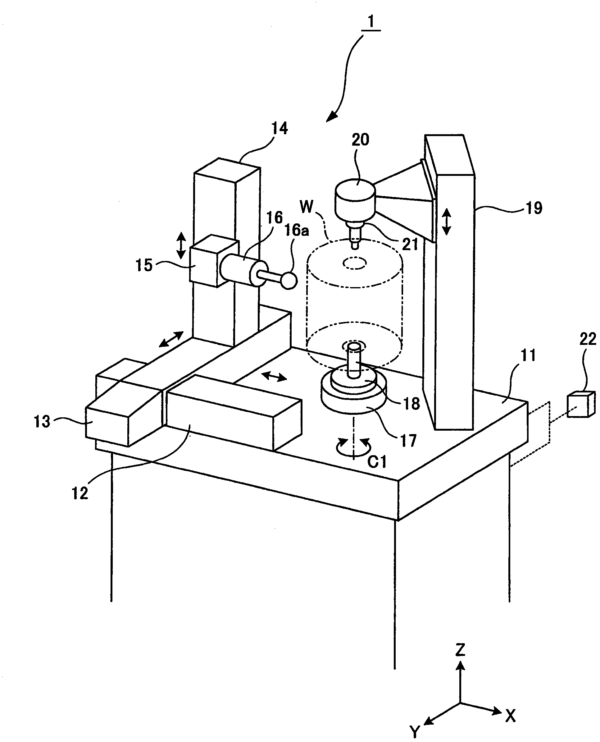
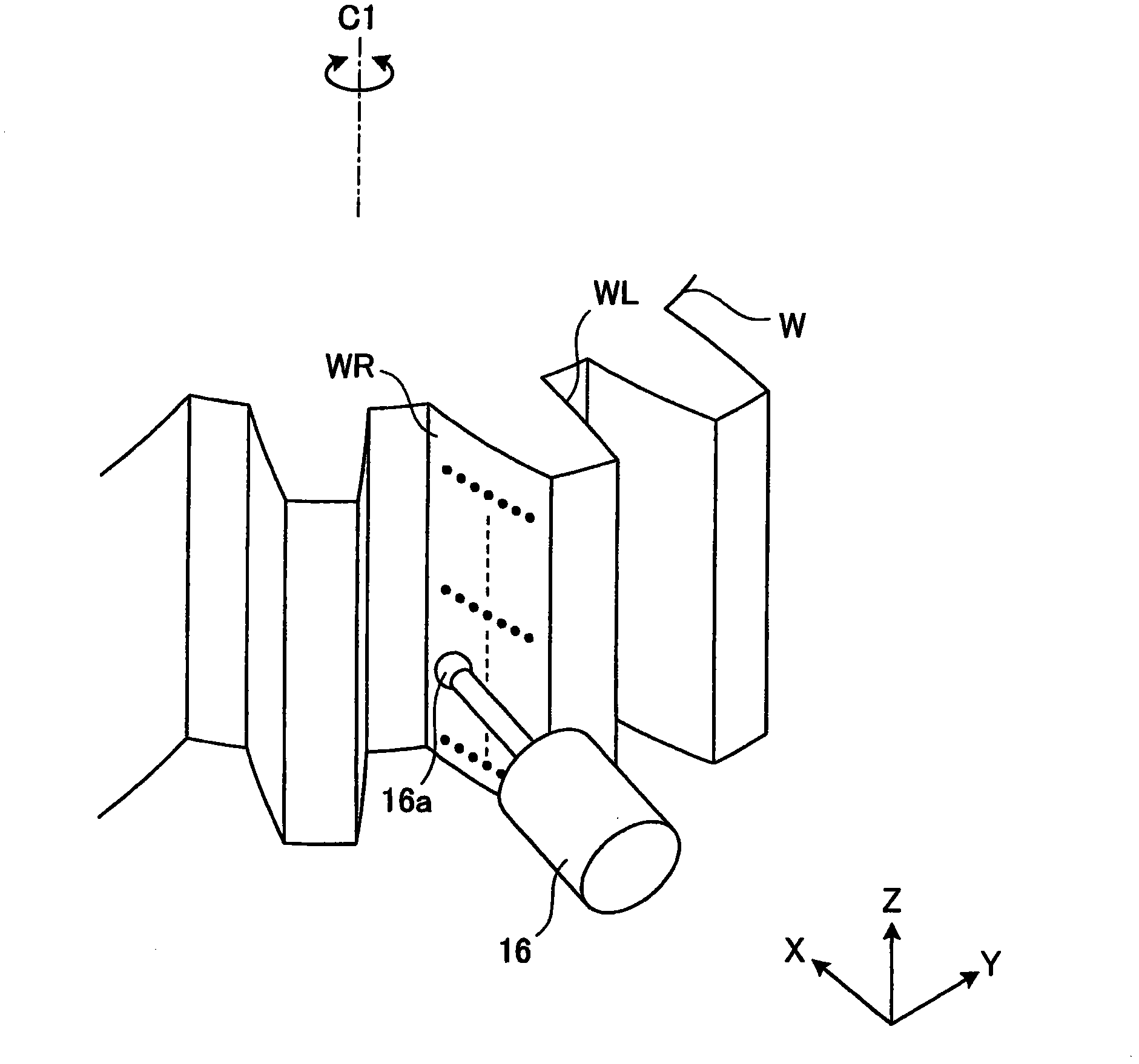
[0022] figure 1 The gear measuring instrument 1 shown is used to measure the tooth profile of a large workpiece (gear to be measured, gear to be processed) W after grinding, such as figure 2 shown.

[0023] Such as figure 1 As shown, a base 11 is provided in the lower part of the gear measuring device 1 . On the upper surface of this base 11 , a guide rail 12 is fixed to extend in the direction of the horizontal X-axis, and a guide rail 13 is slidably supported to extend in the direction of the horizontal Y-axis. The rails 12 and 13 are arranged perpendicular to each other. The guide rail 13 is supported to move in the direction of the X-axis relative to the guide rail 12 . Also, on the guide rail 13 , a guide rail 14 extending in the direction of the vertical Z-axis is supported to move in the direction of the Y-axis.

[0024] On the side surface of the guide rail 14, a movable body 15 is supported so as to be movable up and down in the Z-axis direction. A measuring de...


PUM


Abstract

Provided is a method of measuring a gear wherein the movement range of a stylus is reduced during a measurement by reducing the distance of movement of the stylus in order to downsize a machine. A method for measuring the profile of a gear by performing a synchronizing control on the movement of a stylus and the rotation of a work, and by moving the stylus linearly in a state where the stylus is kept in contact with the right tooth flank or left tooth flank according to the rotation of the work, wherein a tangent touching a contact point which is located after rotation of a predetermined rotation angle a in one direction from a contact point on the base circle of the work, and a tangent touching a contact point which is located after rotation of a predetermined rotation angle a in the opposite direction from a contact point on the base circle of the work are set, the stylus is moved along a tangent when the right tooth flank is measured and moved along another tangent when the left tooth flank is measured, and the intersection of two tangents is set at the middle point between the measurement start position and the measurement end position.

Description

technical field [0001] The invention relates to a gear measurement method for measuring the tooth profile of a gear to be measured. Background technique [0002] In general, when a gear to be machined is machined by a gear cutting machine such as a gear shaping machine, a gear hobbing machine, and a gear grinding machine, after measuring the shape of the tooth surface of at least one machined gear ( After including tooth profile and tooth track), its accuracy is checked, and then the remaining unmachined many gears are machined. Furthermore, in the case of a large gear to be machined, since it is necessary not to generate defects, finishing machining is performed after repeating machining and measurement many times as long as the machining allowance permits. Such measurement of the shape of the tooth flank of the gear to be machined has been performed with a gear measuring machine independent of the gear cutting machine. [0003] However, providing the gear cutting machine...

Claims


Application Information

Patent Timeline
Patent Type & Authority Applications(China)
IPC IPC(8): G01B5/20
CPCG01B5/202G01B3/18G01B5/025
Inventor 大槻直洋柳瀬吉言增尾光一
Owner MITSUBISHI HEAVY IND LTD
Why Eureka
Try Eureka