
Pipeline machine

A pipeline machine and casing technology, which is applied in the field of pipeline machines, can solve the problems of not being able to take it directly when scalded, troublesome, and no protection measures for the water receiving box, so as to reduce taking and running around, ensure safety, and prevent accidental upside-down and fragmentation Effect

Pending Publication Date: 2017-08-11
NINGBO CIXI ELECTRICAL APPLIANCE
View PDF8 Cites 0 Cited by
  • Summary
  • Abstract
  • Description
  • Claims
  • Application Information

AI Technical Summary

Problems solved by technology

When it is necessary to pour many cups of water at the same time, due to the limitation of the water receiving box, it is often necessary to collect two cups of water and run to other places to put them down, and then continue to come over to collect the water.
Sometimes, the water is very hot after pouring and cannot be taken directly or you want to put it away first. The treatment method is usually to put it directly on the water receiving box of the existing water dispenser. If the user cannot come back in time to get the water, it may be cold, resulting in undrinkable
Moreover, the water receiving box does not have any protective measures, and if the cup is placed on it and accidentally touched, it may cause upside-down and broken, resulting in loss, or even endangering the human body

Method used


Image

  • Pipeline machine
  • Pipeline machine
  • Pipeline machine

Examples


Embodiment Construction

[0016] The present invention will be described in further detail below in conjunction with the accompanying drawings and specific embodiments.

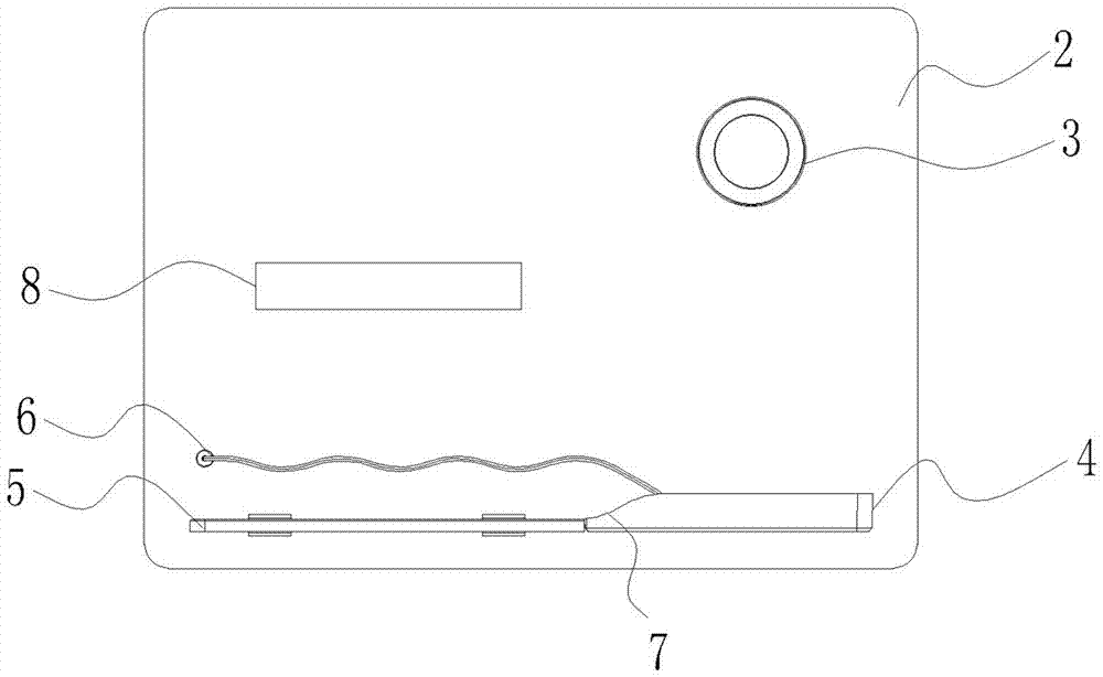
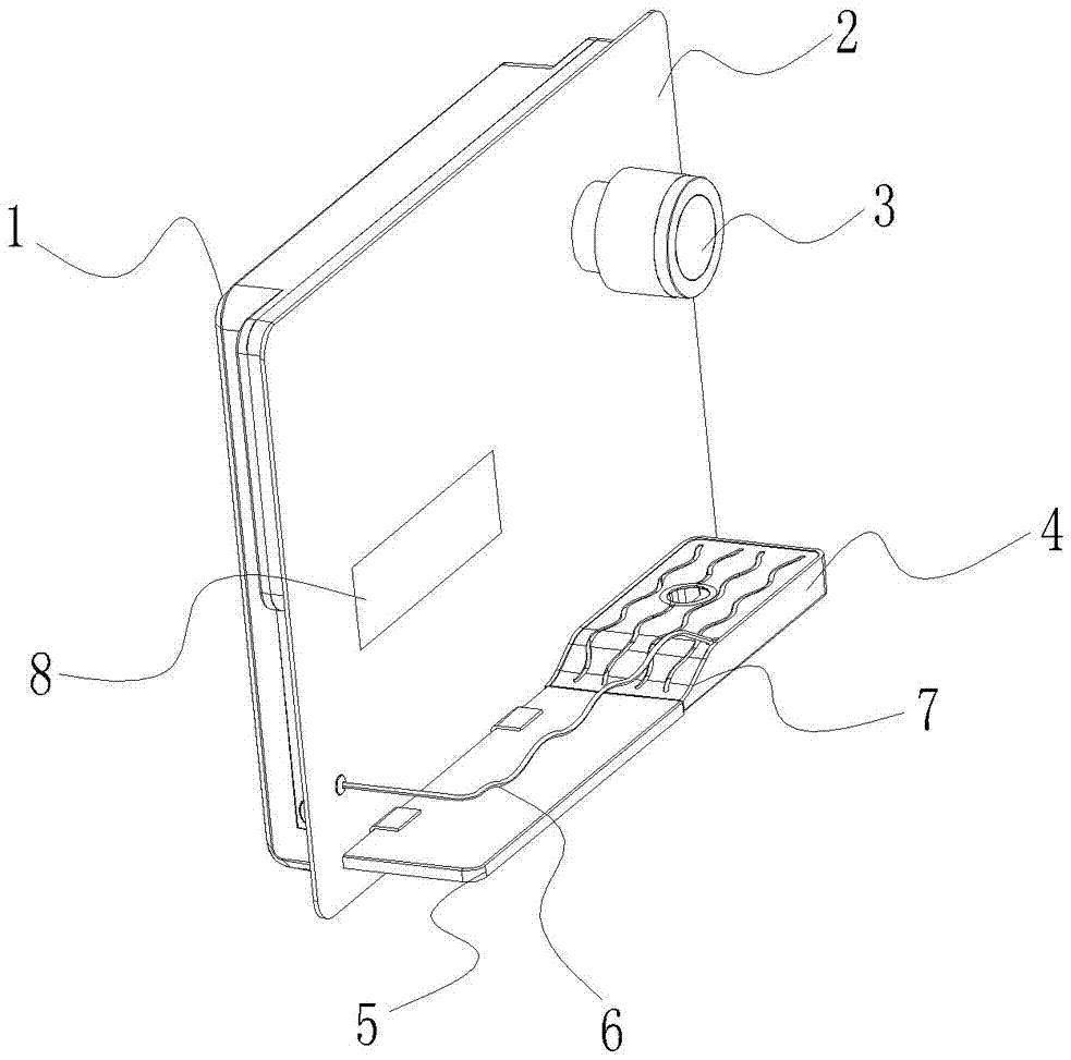
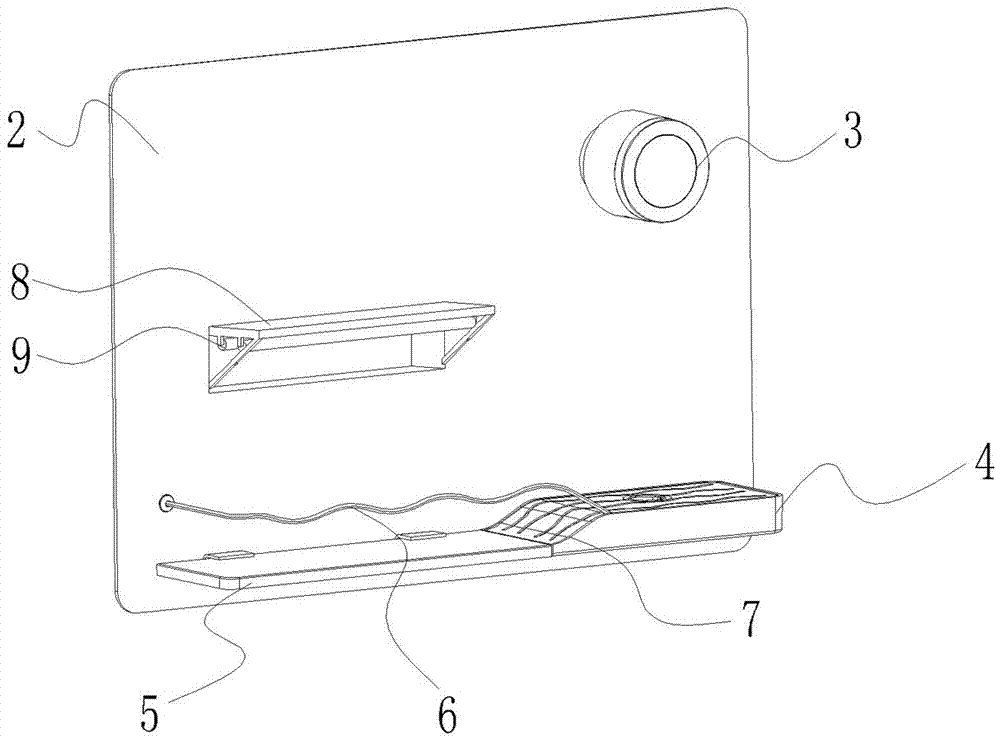
[0017] refer to Figure 1 ~ Figure 3 , a pipeline machine, comprising a casing 1, a circuit board, a heating pipe and a water tank are arranged in the casing 1, and the circuit board is electrically connected with the heating pipe and the water tank respectively, and the front surface of the casing 1 is provided with A decorative plate 2, the decorative plate 2 is provided with a spout 3 and a water receiving box 4 below the spout 3, the spout 3 communicates with the water tank, and the decorative plate 2 protrudes forward A flat plate 5 is provided, and the flat plate 5 is located on one side of the water receiving box 4;

[0018] It also includes a railing 6, one end of the railing 6 is arranged above the end of the flat plate 5 away from the water receiving box 4 and fixed to the decorative plate 2, and the other end of the railin...


PUM


Abstract

The invention discloses a pipeline machine which comprises a machine shell. A circuit board, a heating pipe and a water tank are arranged inside the machine shell. The circuit board is electrically connected with the heating pipe and the water tank separately. A decorative board is arranged on the front surface of the machine shell. The decorative board is provided with a water outlet nozzle and a water receiving box located below the water outlet nozzle. The water outlet nozzle is communicated with the water tank. The decorative board protrudes forwards to be provided with a slab. The slab is located on one side of the water receiving box. The pipeline machine further comprises a handrail. One end of the handrail is arranged above the end, away from the water receiving box, of the slab and is fixedly connected with the decorative board. The other end of the handrail extends along the outer edge of the slab to the end, close to the water receiving box, of the slab. Due to the effect of the slab and the water receiving box, the enough space is adopted for containing a plurality of water cups, no other position needs to be found for containing the water cups, repeated taking and running are avoided, use is easy and convenient, and time and labor are saved; due to the effect of the handrail, the water cups can be prevented from being overturned or broken accidently, the broken water cups and spilled hot water are prevented from injuring the human body, and the safety of the water cups and the safety of the human body are ensured.

Description

technical field [0001] The invention relates to a pipeline machine. Background technique [0002] Pipeline machine, also known as pipeline water dispenser, is generally used in homes, offices, schools, etc., and is used with water purification equipment. It has a built-in water storage PE water tank, and the clean water is placed in the PE water tank in advance, and then heated by a heating tank and made of ice. Refrigeration, hot water and cold water for human consumption. [0003] Existing water dispensers, including pipeline machines, mostly have their own water receiving boxes. The size of the water receiving boxes generally corresponds to the hot and cold water spouts. Most of the water receiving boxes can hold two cups of normal size. When it is necessary to pour many cups of water at the same time, due to the limitation of the water receiving box, it is often necessary to collect two cups of water and run to other places to put them down, and then continue to come to...

Claims


Application Information

Patent Timeline
IPC IPC(8): A47J31/00A47J31/44A47J31/54A61L2/10
CPCA61L2/10A47J31/00A47J31/4403A47J31/54
Inventor 金军方曙光胡孟溪郑丽燕沈林王自立
Owner NINGBO CIXI ELECTRICAL APPLIANCE
Learn More