Air frying pan

A technology of air fryer and frying basket, which is applied in kitchen utensils, household utensils, roasters/barbecue grids, etc., to achieve the effects of even heating of food, easy cleaning, and simple processing technology

Active Publication Date: 2015-04-08
严绍基
View PDF6 Cites 83 Cited by
  • Summary
  • Abstract
  • Description
  • Claims
  • Application Information

AI Technical Summary

Problems solved by technology

[0003] The purpose of the present invention is to overcome the problems existing in the existing air fryer, and to provide an air fryer with simple structure, easy processing and easy cleaning of the bottom of the pan.

Method used


Image

  • Air frying pan
  • Air frying pan
  • Air frying pan

Examples


Embodiment 1

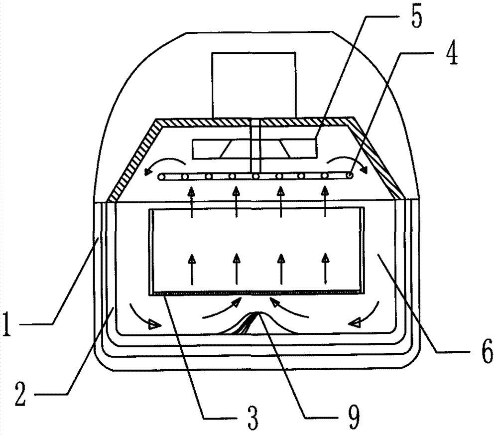
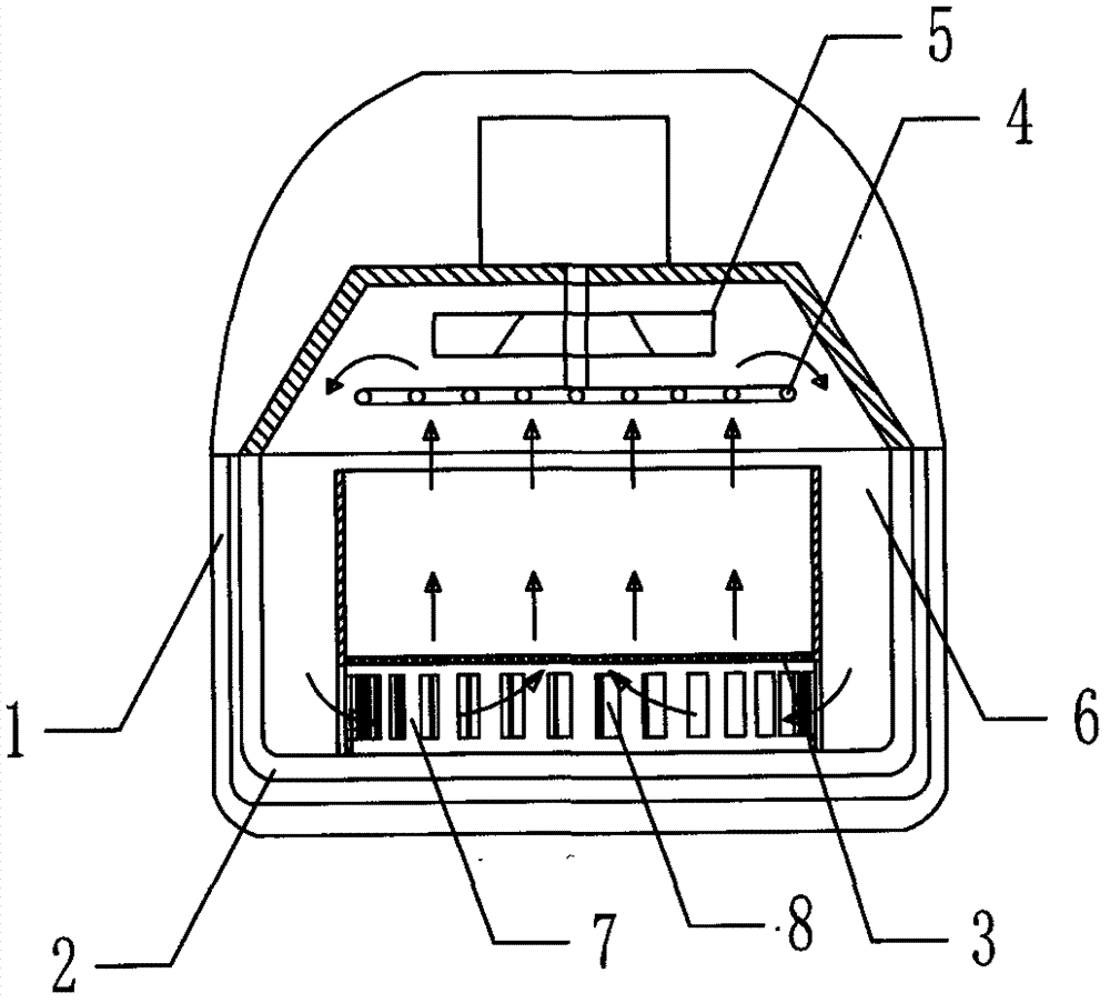
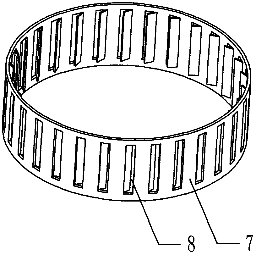
[0018] Embodiment one: if figure 2 , image 3 As shown, in the air fryer of this embodiment, the pot body 1 has an inner container 2 as a food baking chamber, a frying basket 3 for loading food is arranged in the inner container 2, and an electric heating tube is also provided above the frying basket 3 4 and the fan 5 located above the electric heating tube 4, the side wall of the frying basket 3 is a thin plate, and the bottom is a grid, and an airflow channel 6 is formed between the inner tank 2 and the frying basket 3. In order to facilitate the airflow circulation and support stability, the The outer periphery of the bottom of the frying basket 3 extends downwards with a guide tube 7 of a cylindrical structure. The lower end of the guide tube 7 is preferably directly supported on the bottom wall of the inner container 2, and the gap between the two is as small as possible, so that the guide tube The air intake slant hole 8 is provided on the side wall of the flow tube 7,...

Embodiment 2

[0019] Embodiment two: if Figure 4 As shown, the main structure of the air fryer of this embodiment is basically the same as that of Embodiment 1. The difference is that the support body 7 has a structure with a large opening at the upper end and a small opening at the lower end. The guide tube 7 of this structure, The airflow flows more smoothly, and the swirling airflow guided by the air intake inclined hole 8 spreads upward faster.

Embodiment 3

[0020] Embodiment three: as Figure 5 As shown, the main structure of the air fryer of this embodiment is basically the same as that of Embodiment 1, the difference is that the guide cylinder 7 is a structure with a large opening diameter at the upper and lower ends and a relatively small diameter at the middle, and the inclined air inlet hole 8 It is installed on the side wall of the lower part of the air guide tube 7. The guide tube 7 with this structure is conducive to accelerating the airflow velocity in the small diameter of the middle part, thereby improving the penetration of the airflow through the bottom of the frying basket 3 and the food gap. .

[0021] A further advantage is that the side wall of the deflector tube extends upwards to be movably socketed with the frying basket 3, and the side wall and the bottom wall of the frying basket 3 can be integrally formed by grids, which will significantly reduce the overall weight of the frying basket 3. It is more conven...


PUM


Abstract

The invention belongs to the field of family kitchen electric appliance manufacturing and specifically relates to an air frying pan. The air frying pan is mainly composed of a pan body (1), a liner (2), a frying basket (3) arranged in the liner (2), an electric heating pipe (4) arranged above the frying basket (3) and a fan (5) located above the electric heating pipe (4); the sidewalls of the frying basket (3) are formed by metal sheets and the bottom of the frying basket (3) is formed by a screen; an air flow channel (6) is arranged between the liner (2) and the frying basket (3); the air frying pan is characterized in that the outer periphery of the bottom of the frying basket (3) extends downwards to form a guide cylinder (7) and air inflow inclined holes (8) for guiding airflow to rotate are evenly formed in the sidewall of the guide cylinder (7). The air inflow inclined holes (8) are leftward or rightward slit holes toward the same direction. The air frying pan of such a structure has the advantages that the frying basket is simple in structure, the bottom of the liner is easy to manufacture and easy to clear, and is well supported.

Description

technical field [0001] The invention belongs to the field of household kitchen appliance manufacturing, and in particular relates to an air fryer which simultaneously utilizes heat radiation and hot air flow to bake food. Background technique [0002] Such as figure 1 As shown, the existing air fryer usually has a raised air guide on the bottom wall of the inner pot, such as in Chinese patent ZL200880131179.7, the pot body 1 has a food baking chamber, and the inner pot 2 is arranged on the pot body 1, the bottom of the food baking chamber, the frying basket 3 is arranged in the inner container 2, and an electric heating tube 4 and a fan 5 located above the heating tube 4 are arranged above the frying basket 3. The side wall of the frying basket 3 is a flat plate 30 , the bottom is a grid plate 31, an air flow channel 6 is provided between the inner tank 2 and the frying basket 3, and at least one guide body 9 in a complex convex-concave shape is provided at the center of th...

Claims


Application Information

Patent Timeline
Patent Type & Authority Applications(China)
IPC IPC(8): A47J37/06
CPCA47J37/0641
Inventor 肖学宇
Owner 严绍基
Why Eureka
Try Eureka