Method and system for a light source assembly supporting direct coupling to an integrated circuit

a light source assembly and integrated circuit technology, applied in the field of optoelectronic communications, can solve the problems of cable bulk penalties, large power requirements, and complex structure, and achieve only modest improvements in reach and limited scalability

Active Publication Date: 2012-05-01
CISCO TECH INC
View PDF9 Cites 85 Cited by
  • Summary
  • Abstract
  • Description
  • Claims
  • Application Information

AI Technical Summary

Problems solved by technology

They can be mitigated to some extent with equalization, coding, and shielding, but these techniques require considerable power, complexity, and cable bulk penalties while offering only modest improvements in reach and very limited scalability.

Method used


Image

  • Method and system for a light source assembly supporting direct coupling to an integrated circuit
  • Method and system for a light source assembly supporting direct coupling to an integrated circuit
  • Method and system for a light source assembly supporting direct coupling to an integrated circuit

Examples


Embodiment Construction

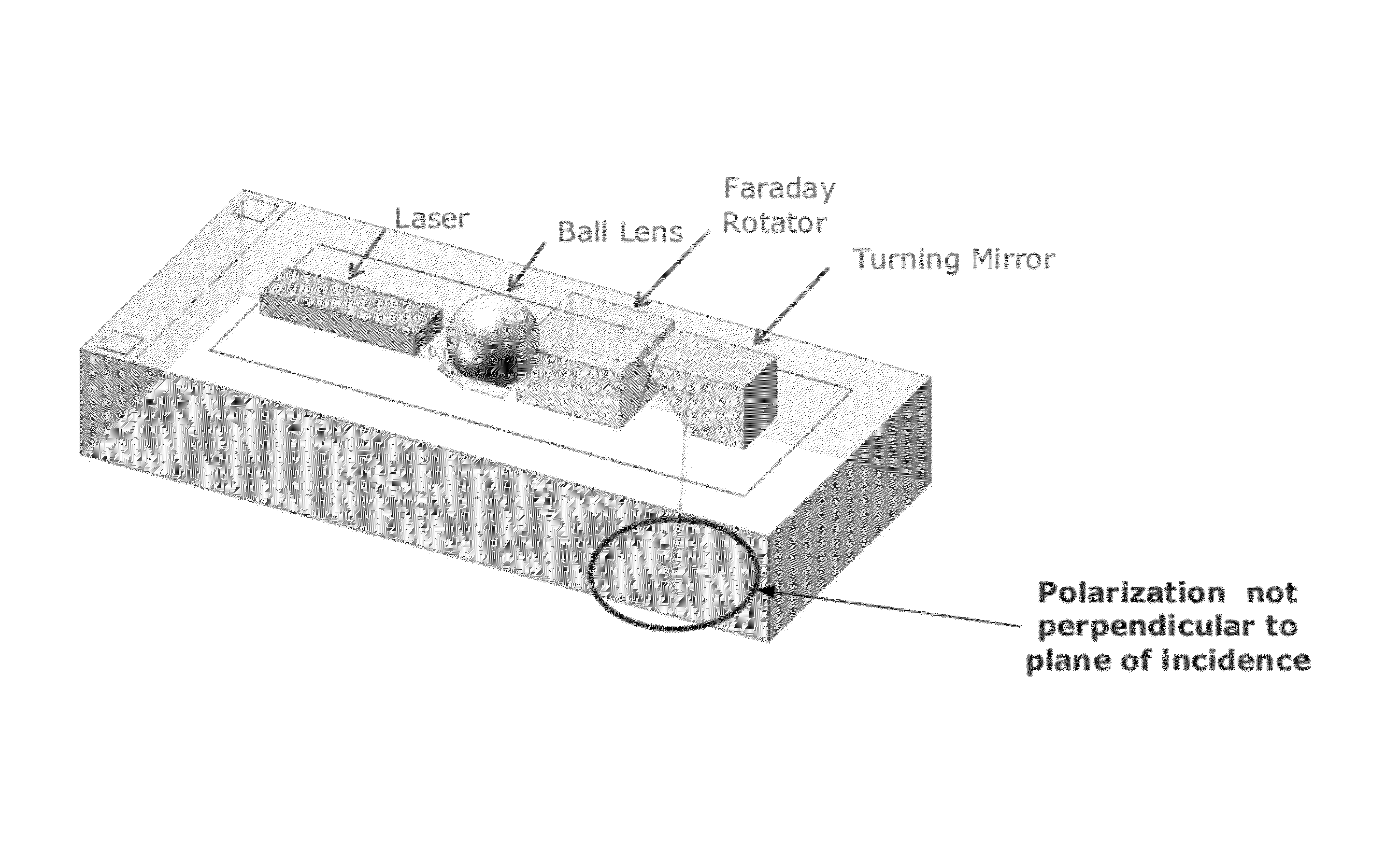
[0066]Certain aspects of the invention may be found in a method and system for a light source assembly supporting direct coupling to an integrated circuit. In various exemplary aspects of the invention, a light source assembly affixed to the chip may comprise a laser, a microlens, a turning mirror, an optical bench, and reciprocal and non-reciprocal polarization rotating elements. The laser may generate an optical signal that may be focused utilizing the microlens, which may comprise a ball lens. The focused optical signal may be reflected at an angle defined by the turning mirror. The reflected optical signal may be transmitted out of the light source assembly to one or more grating couplers in the photonically enabled CMOS chip. The one or more grating couplers may comprise polarization independent optical couplers. The laser may comprise an edge-emitting semiconductor laser diode and / or a feedback insensitive laser diode. The light source assembly may comprise two electro-thermal...


PUM

PropertyMeasurementUnit
wavelengthaaaaaaaaaa
incident angleaaaaaaaaaa

Abstract

Methods and systems for a light source assembly supporting direct coupling to a photonically enabled complementary metal-oxide semiconductor (CMOS) chip are disclosed. The assembly may include a laser, a microlens, a turning mirror, reciprocal and / or non-reciprocal polarization rotators, and an optical bench. The laser may generate an optical signal that may be focused utilizing the microlens. The optical signal may be reflected at an angle defined by the turning mirror, and may be transmitted out of the light source assembly to one or more grating couplers in the chip. The laser may include a feedback insensitive laser. The light source assembly may include two electro-thermal interfaces between the optical bench, the laser, and a lid affixed to the optical bench. The turning mirror may be integrated in a lid affixed to the optical bench or may be integrated in the optical bench.

Description

CROSS-REFERENCE TO RELATED APPLICATIONS / INCORPORATION BY REFERENCE[0001]This application makes reference to and claims priority to U.S. Provisional Application Ser. No. 61 / 079,358 filed on Jul. 9, 2008, which is hereby incorporated herein by reference in its entirety.[0002]This application also makes reference to: U.S. Patent Application Ser. No. 61 / 190,857 filed on Sep. 3, 2008.[0003]Each of the above stated applications is hereby incorporated herein by reference in its entirety.FEDERALLY SPONSORED RESEARCH OR DEVELOPMENT[0004][Not Applicable]MICROFICHE / COPYRIGHT REFERENCE[0005][Not Applicable]FIELD OF THE INVENTION[0006]Certain embodiments of the invention relate to optoelectronic communications. More specifically, certain embodiments of the invention relate to a method and system for a light source assembly supporting direct coupling to an integrated circuit.BACKGROUND OF THE INVENTION[0007]Optical communication has revolutionized how information is transmitted. Mass-produced sem...

Claims


Application Information

Patent Timeline
Patent Type & Authority Patents(United States)
IPC IPC(8): G02F1/01G01N21/86G02B5/30G01J3/447
CPCG02B6/34H04B10/503G02B6/4214G02B6/43G02B26/105G02B6/4208G02B6/305G02B6/32H01S5/005H01S5/0064H01S5/187
Inventor MACK, MICHAELPETERSON, MARKGLOECKNER, STEFFENNARASIMHA, ADITHYARAMKOUMANS, ROGERDE DOBBELAERE, PETER
Owner CISCO TECH INC
Why Eureka
Try Eureka