
Electrocaloric refrigerator and multilayer pyroelectric energy generator

a technology of pyroelectric energy generator and electrocaloric refrigerator, which is applied in the direction of domestic cooling equipment, lighting and heating equipment, support, etc., can solve the problems of moving parts or fluids, less efficient solid-state thermoelectric devices than vapor compression devices, and inability to meet the needs of use,

Inactive Publication Date: 2010-07-15
STC UNM
View PDF12 Cites 79 Cited by
  • Summary
  • Abstract
  • Description
  • Claims
  • Application Information

AI Technical Summary

Benefits of technology

The patent describes an active heat exchanger device and a method of cooling a fluid using a single-layer heat engine. The device includes a channel that allows the fluid to flow through and be cooled by the heat engine. The method involves creating temperature differences between the heat engine and the reservoirs to extract electrical power. The technical effects of this invention include improved cooling efficiency and increased power generation.

Problems solved by technology

While the solid state thermoelectric devices are much less efficient than vapor compression devices, they are compact and without moving parts or fluids.
Both of these technologies are mature and are unlikely to improve much in the foreseeable future.
There have been small efforts to develop electrocaloric or magnetocaloric refrigerators, but practical and economic obstacles have prevented their use in practical coolers.
1233-1240, 1981) to develop a cryogenic electrocaloric refrigerator were unsuccessful because the electric fields needed for the required temperature swings were larger than the breakdown fields.
Furthermore, most of the effort in directly extracting electrical energy from heat utilizes some type of thermoelectric material.
However, no major breakthroughs have occurred.
Pyroelectric energy conversion has been examined for many years, but little progress has been made in developing practical systems.

Method used


Image

  • Electrocaloric refrigerator and multilayer pyroelectric energy generator
  • Electrocaloric refrigerator and multilayer pyroelectric energy generator
  • Electrocaloric refrigerator and multilayer pyroelectric energy generator

Examples


Embodiment Construction

[0028]Reference will now be made in detail to the present embodiments, examples of which are illustrated in the accompanying drawings. Wherever possible, the same reference numbers will be used throughout the drawings to refer to the same or like parts.

[0029]Notwithstanding that the numerical ranges and parameters setting forth the broad scope of the invention are approximations, the numerical values set forth in the specific examples are reported as precisely as possible. Any numerical value, however, inherently contains certain errors necessarily resulting from the standard deviation found in their respective testing measurements. Moreover, all ranges disclosed herein are to be understood to encompass any and all sub-ranges subsumed therein. For example, a range of “less than 10” can include any and all sub-ranges between (and including) the minimum value of zero and the maximum value of 10, that is, any and all sub-ranges having a minimum value of equal to or greater than zero an...


PUM


Abstract

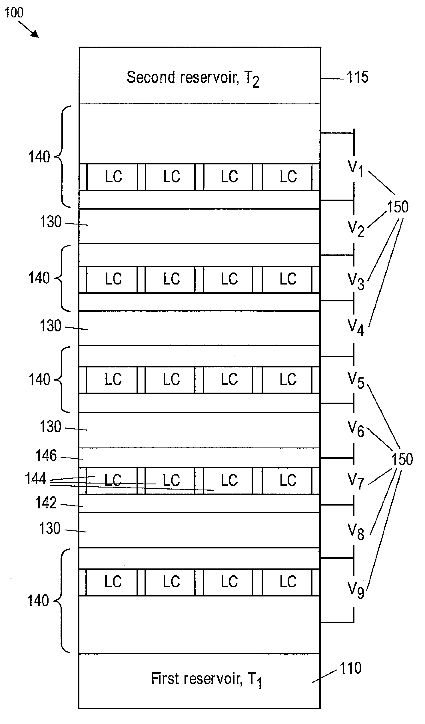
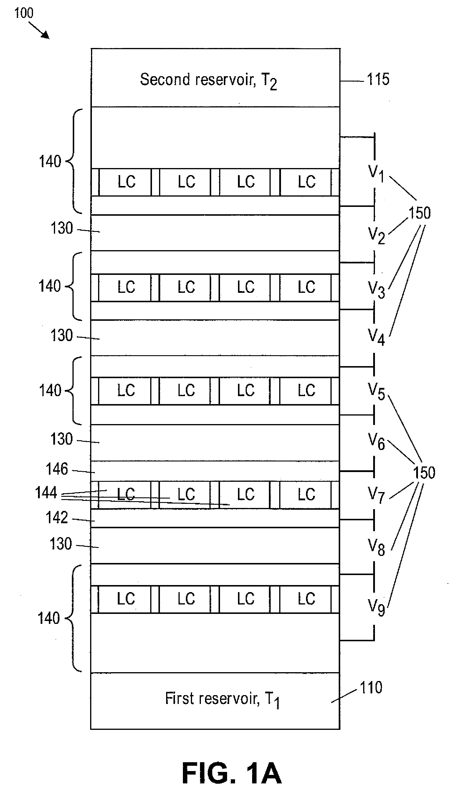
Provided are electrocaloric devices, pyroelectric devices and methods of forming them. A device which can be a pyroelectric energy generator or an electrocaloric cooling device, can include a first single-layer heat engine having a first side configured to be in contact with a first reservoir and a second side configured to be in contact with a second reservoir, wherein the first reservoir comprises a fluid. The device can also include a second single-layer heat engine having a first side in contact with the first reservoir and a second side in contact with a third reservoir and a channel disposed between the first single-layer heat engine and the second single-layer heat engine, the channel configured to transport the fluid from a first end to a second end. The device can further include one or more power supplies configured to apply voltages to the first and the second single-layer heat engine.

Description

RELATED APPLICATIONS[0001]This application is a continuation-in-part of U.S. patent application Ser. No. 12 / 354,436, entitled “Electrostatic Refrigeration And Multilayer Pyroelectric Energy Generator,” filed Jan. 15, 2009, which is hereby incorporated by reference in its entirety.GOVERNMENT RIGHTS[0002]This invention was made with government support under Contract No. FA9550-04-1-0356 awarded by the Air Force Office of Scientific Research. The government has certain rights in the invention.FIELD OF THE INVENTION[0003]The subject matter of this invention relates refrigeration and power generators. More particularly, the subject matter of this invention relates to devices and methods of making active heat exchanger electrocaloric refrigerators and pyroelectric energy generators.BACKGROUND OF THE INVENTION[0004]Currently, the great majority of devices for near room-temperature refrigeration and air conditioning are based on vapor compression technology. In some small niche applications...

Claims


Application Information

Patent Timeline
Patent Type & Authority Applications(United States)
IPC IPC(8): F25B21/02F28F27/00F25D25/00H05K7/20
CPCF25B21/00Y02B30/66H01L37/02F25B2321/001Y02B30/00H10N15/10
Inventor MALLOY, KEVIN J.EPSTEIN, RICHARD I.
Owner STC UNM
Learn More