Side sealing device, sintering pallet and sintering machine

A technology of side seals and locomotives, which is applied in the direction of engine seals, mechanical equipment, engine components, etc., can solve problems that affect production progress, time-consuming, heavy workload, etc., reduce production and maintenance costs, and overcome the difficulty of seals. The effect of easy wear and maintenance

Active Publication Date: 2013-08-14
宝鸡市晋旺达机械设备有限公司
View PDF4 Cites 0 Cited by
  • Summary
  • Abstract
  • Description
  • Claims
  • Application Information

AI Technical Summary

Problems solved by technology

Although the side seal can overcome the lack of easy wear of the seals in the traditional sliding plate-slideway compression seal structure, the air leakage is low and the air volume utilization rate is improved, but because the sealing plate is installed on the top of the sintering machine bellows, if local wear and leakage occur , it is necessary to stop the machine for inspection and maintenance of the entire sealing plate, which not only has a large workload, but also takes time and affects the production progress

Method used


Image

  • Side sealing device, sintering pallet and sintering machine
  • Side sealing device, sintering pallet and sintering machine
  • Side sealing device, sintering pallet and sintering machine

Examples


Embodiment 1

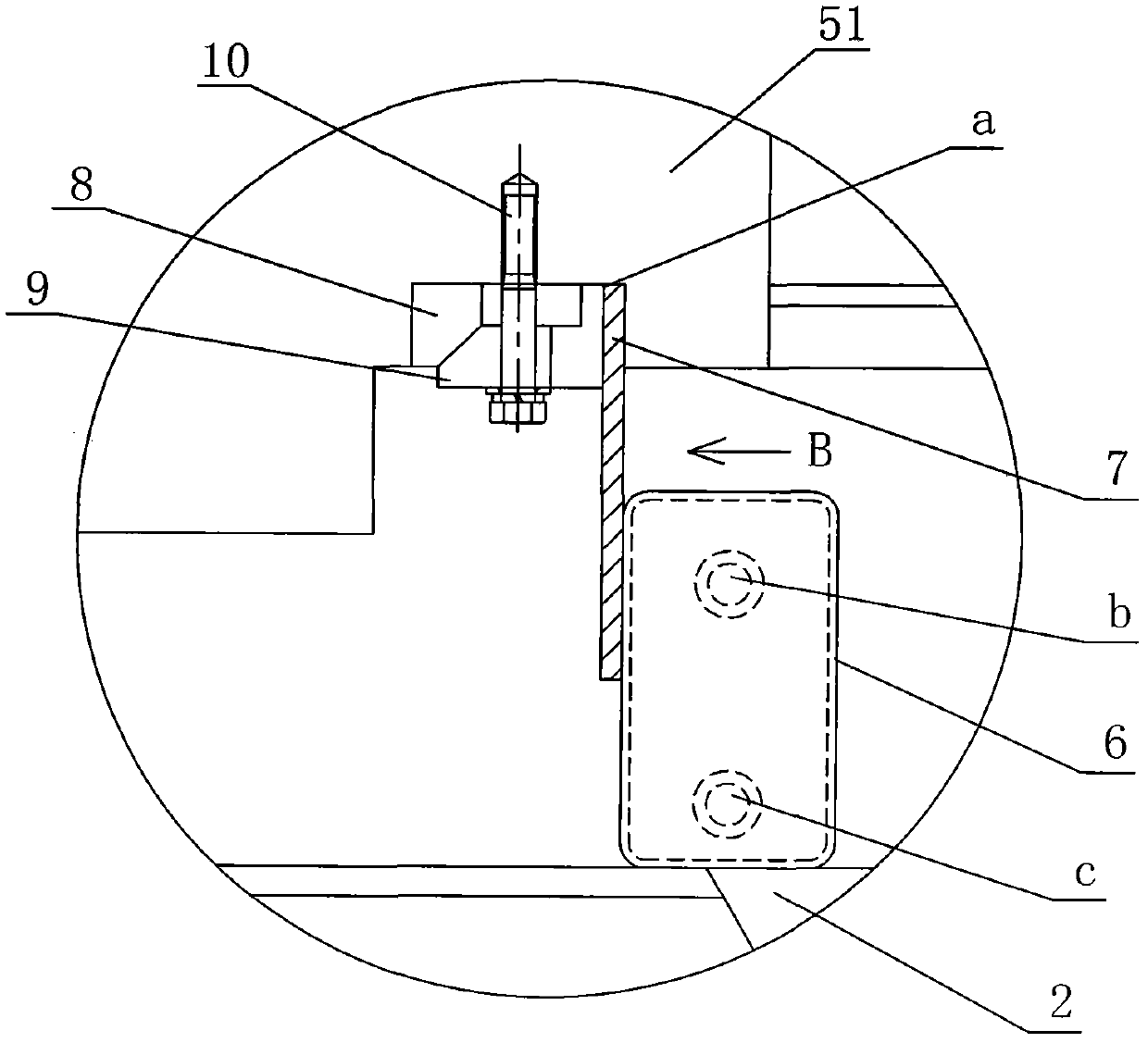
[0030] Such as figure 1 , figure 2 and image 3 As shown, in the sintering equipment, the sintering machine trolley 5 is set above the bellows 2. During the sintering process, the sintering machine trolley 5 moves above the bellows 2 along the track 4, and completes sintering after material distribution, ignition, sintering, and cooling to the tail of the machine. After the whole process, the sintering machine trolley 5 turns the sintered ore in it into the sintering ore trough, and then the sintering machine trolley 5 returns to the starting position through the empty lane, and repeats the above-mentioned cyclic sintering process. The sintering machine trolley 5 includes trolley wheels 50, a trolley body 51, a trolley fence 52 arranged on the trolley body 51, a heat insulating element 53 installed in the trolley body 51, and a heat insulating element 53 arranged on the top of the heat insulating element 53. The castor bar 54. For the convenience of the following descripti...

Embodiment 2

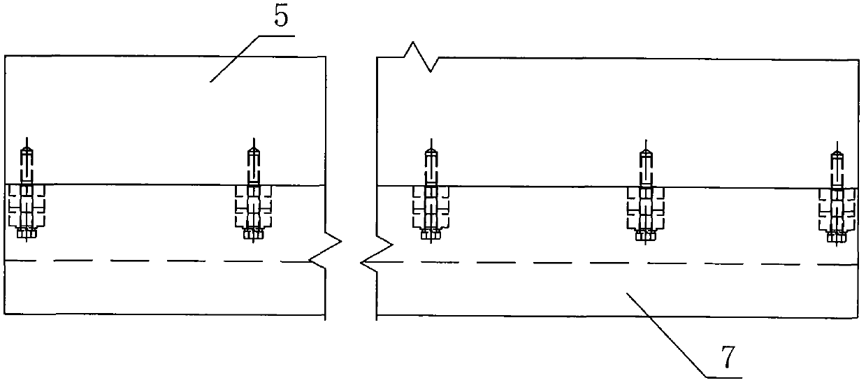
[0036] Such as Figure 8 As shown, the difference between this embodiment and Embodiment 1 is that the trolley wheel 50 is installed on the mounting frames 3 on both sides of the bellows 2 through the wheel mounting frame 55, forming a roller track on which the sintering machine trolley 5 runs, The left and right outer sides of the lower part of the trolley body 51 are processed with trolley support wheel limit guide grooves d extending from front to rear. The sintering machine trolley 5 is supported above the bellows 2 by the trolley wheels 50. The sintering machine trolley of this embodiment And the structure of the sintering machine and the applicant's patent application number are 201120028769.6, the name of invention is the same as the sintering machine trolley and the sintering machine structure of the roller support type sintering trolley and sintering machine. A sealing plate 7 is arranged in the limit guide groove d of the supporting wheel of the trolley. The sealing ...


PUM

PropertyMeasurementUnit
thicknessaaaaaaaaaa
heightaaaaaaaaaa

Abstract

The invention discloses a sintering machine, a sintering pallet and a side sealing device. The sintering machine comprises a main frame, a discharge mechanism, a crusher and a mineral aggregate conveyer, wherein the main frame is provided with a sintering bin, a distribution mechanism, an ignition furnace, a heat insulation furnace, an air box, a rail, a mounting rack, a windshield wall, an ash bucket, an ash clearing valve and a pusher; the main frame is positioned above the air box and provided with the sintering pallet; the sintering pallet is supported on the rail through pallet wheels; the sintering pallet comprises a pallet body and pallet breast boards, wherein a heat insulation piece and a grate positioned above the heat insulation piece are arranged in the pallet body; the palletbreast boards are arranged at two sides of the pallet body; and a sealing plate is fixed at the bottom of the pallet body through a sealing plate mounting member, and the inner lateral surface of thesealing plate is in contact with the outer lateral surface of the windshield wall at the top of the air box. The sealing plate is fixed on the sintering pallet, so that only the sealing plate on eachsintering pallet is examined and maintained, halting maintenance is not needed, and equipment operation and maintenance costs are reduced.

Description

technical field [0001] The invention relates to sintering equipment and auxiliary devices in the sintering equipment in the field of smelting, in particular to a sintering machine, a sintering machine trolley and a side sealing device for side sealing the gap between the sintering machine trolley and the bellows. Background technique [0002] In steel production, sintering production is one of the important processes, which provides high-quality raw materials for blast furnace ironmaking. In the existing sintering system, the sintering machine trolley is located above the bellows of the sintering machine. After the sintering machine trolley is filled with the mixture, it runs on the trolley rails on both sides of the bellows box. The top of the mixture is ignited through the ignition furnace, and the bellows is placed on the sintering machine platform. The lower part of the car draws air, so that the mixture is sintered downward from the top of the sintering machine trolley....

Claims


Application Information

Patent Timeline
Patent Type & Authority Patents(China)
IPC IPC(8): F27B21/08F16J15/16
Inventor 关兴旺关珍旺
Owner 宝鸡市晋旺达机械设备有限公司
Why Eureka
Try Eureka