Sealing device for sintering machine trolley and air box

A technology of sealing device and machine trolley, which is applied in the direction of engine sealing, mechanical equipment, engine components, etc., can solve the problems of air leakage from the bellows and the bench workshop, inability to reduce costs, and increase processing capacity, and achieve sintering. Low investment, low production cost, overcoming the effect of easy wear and tear

Active Publication Date: 2012-05-23
宝鸡市晋旺达机械设备有限公司
View PDF2 Cites 2 Cited by
  • Summary
  • Abstract
  • Description
  • Claims
  • Application Information

AI Technical Summary

Problems solved by technology

[0006] The above-mentioned sealing devices use different methods to overcome the deficiencies of the sliding plate-slideway seal, but they all have the disadvantages of many parts and complex structures, which increase the amount of additional processing in the manufacturing stage, cannot reduce costs, and cannot Solve the air leakage problem between the bellows and the workshop

Method used


Image

  • Sealing device for sintering machine trolley and air box
  • Sealing device for sintering machine trolley and air box
  • Sealing device for sintering machine trolley and air box

Examples


Embodiment 1

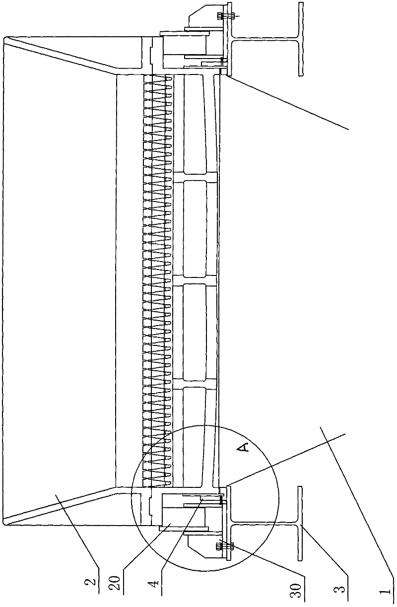
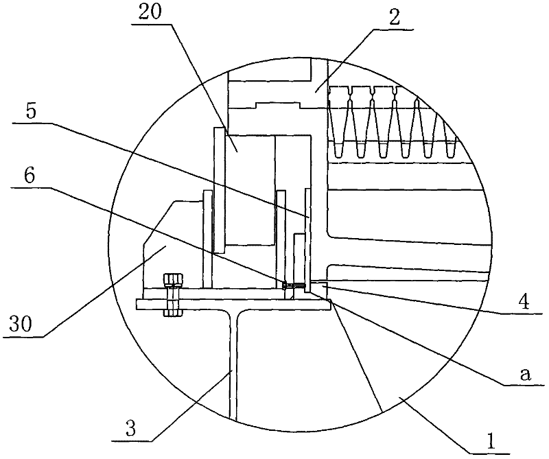
[0031] like figure 1 and figure 2 As shown, a sintering machine trolley 2 is arranged above the bellows 1 in the sintering system. During the sintering process, the sintering machine trolley 2 moves forward along the track above the bellows 1. For the convenience of description, the traveling of the sintering machine trolley 2 The direction is defined as the longitudinal direction, and the direction of the width direction of the sintering machine trolley 2 is defined as the transverse direction.

[0032] Trolley wheels 20 are arranged under the left and right outer sides of the sintering machine trolley 2, and the sintering machine trolley 2 is supported on the bellows 1 through the trolley wheels 20, and longitudinally extending mounting brackets 3 are respectively installed on the two outer sides of the top of the bellows 1 , the mounting bracket 3 is mounted with a wheel fixing frame 30 through a threaded fastening connector, the trolley wheel 20 of the present embodiment...

Embodiment 2

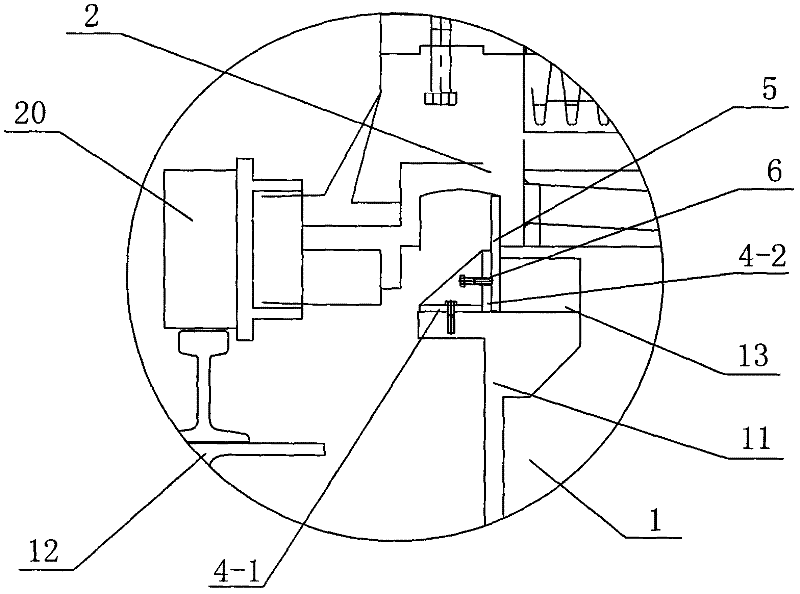
[0035] like image 3 and Figure 4As shown, the difference between this embodiment and Embodiment 1 is that the two outer sides of the top of the bellows 1 are installed with a longitudinally extending slide rail mounting bracket 11 and a wheel track bracket 12 through a threaded fastening connector, and the slide rail mounting bracket 11 is located on the wheel. The inner side of the track support 12 is the same as the existing sintering machine, and trolley wheels 20 are installed on the bottom two outer sides of the sintering machine trolley 2. The trolley wheels 20 are arranged on the track installed on the wheel track support 12, and the sintering machine trolley 2 The trolley wheel 20 is supported on the bellows 1 , and the trolley wheel 20 moves along the track to drive the sintering machine trolley 2 to travel. The slide rail mounting bracket 11 is located below the outside of the bottom of the bellows 1, and a slide rail 13 is installed on the slide rail mounting bra...

Embodiment 3

[0037] Such as Figure 5 As shown, the difference between this embodiment and Embodiment 2 is that the sealing mounting base 4 is integrally formed with a compression back plate 4-3, and the compression back plate 4-3 is located on the vertical side of the horizontal bottom plate 4-1. The inner side of the plate 4-2, the lower part of the sealing plate 5 is fixedly installed in the groove formed between the vertical side plate 4-2 and the compression back plate 4-3, and the compression back plate 4-3 is used for sealing the sealing plate 5. A pressing plane is provided to realize the functions of fixing the sealing plate 5 and completing the sealing. The top bolt 6 passes through the end of the vertical side plate 4-2 of the sealing mounting seat 4 and pushes against the bottom of the sealing plate 5. When the top bolt 6 is tightened, the sealing plate 5 can be tightly pressed against the side of the back plate 4-3. In contact, the top of the sealing plate 5 is attached to th...


PUM


Abstract

The invention discloses a sealing device for a sintering machine trolley and an air box. The sealing device comprises a sealing plate and a sealing plate mounting member, wherein the sealing plate is arranged on the outer side surface of the lower part of the sintering machine trolley so as to seal a clearance between the bottom of the sintering machine trolley and the top of the air box; and thesealing plate mounting member is used for mounting the sealing plate on a mounting bracket at the outer side of the top of the air box. According to the sealing device disclosed by the invention, as the clearance between the sintering machine trolley and the air box is sealed from the side surface, the air leakage rate is low, the airflow utilization rate is improved by 30%, the sintering yield is increased by 20%, the total power of the motor is reduced by 30%, the production cost is low, the equipment operation rate is high, and the maintenance is convenient. By adopting the sealing device disclosed by the invention, the investment in civil engineering is saved by about 40%, the investment in sintering is saved, and the operation cost is low.

Description

technical field [0001] The invention relates to an auxiliary device for sintering equipment in the field of smelting, in particular to a sealing device for sealing the gap between the sintering machine trolley and the bellows in the running direction of the sintering machine trolley. Background technique [0002] In steel production, sintering production is one of the important processes, which provides high-quality raw materials for blast furnace ironmaking. In the existing sintering system, the bellows of the sintering machine are set under the trolley of the sintering machine. After the trolley of the sintering machine is filled with the mixture, it runs on the trolley rails on both sides of the bellows. The top of the mixture is ignited through the ignition furnace. The lower part of the trolley draws air so that the mixture is sintered downward from the top of the sintering machine trolley. In order to achieve a good ventilation effect for the bellows, it is necessary t...

Claims


Application Information

Patent Timeline
Patent Type & Authority Patents(China)
IPC IPC(8): F27B21/08F16J15/16
Inventor 关兴旺关珍旺
Owner 宝鸡市晋旺达机械设备有限公司
Why Eureka
Try Eureka