Pipe accessing device

A technology for connecting devices and pipes, which is applied in indoor sanitary pipe devices, water supply devices, buildings, etc. It can solve the problems of occupying indoor space, unsatisfactory, noise, etc., and achieves the effects of reliable performance, simple structure, and convenient use

Active Publication Date: 2012-01-25
王凤蕊
View PDF8 Cites 1 Cited by
  • Summary
  • Abstract
  • Description
  • Claims
  • Application Information

AI Technical Summary

Problems solved by technology

[0002] At present, there are many problems in the drainage system, such as leakage, odor return, noise, etc., especially the pollution of leakage and odor return is particularly prominent; in order to solve the above problems, many technicians have proposed different solutions for the above problems: 1. In the special single standpipe system, a hollow water flow is formed by setting a water channel at the junction of the horizontal pipe and the standpipe, so as to improve the ventilation capacity of the drainage standpipe and reduce the odor return of the floor drain; 2. Adopt the double standpipe method and set a special Ventilation pipe to reduce the problem of floor drain odor return; 3. Adopt double standpipe self-circulation mode to improve the exhaust capacity of the standpipe and reduce the problem of floor drain odor return; 4. In the special long joint single standpipe system, because the standpipe is partially enlarged, the The interior decoration has a certain impact and occupies indoor space; the above technologies have solved the floor drain problem to varying degrees, but they are not ideal. In use, there is still the problem of water seal pollution

Method used


Image

  • Pipe accessing device
  • Pipe accessing device

Examples


Embodiment 1

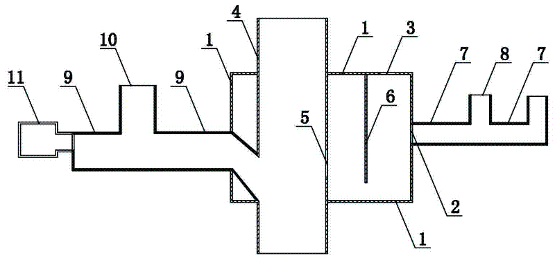
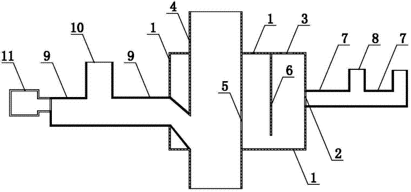
[0019] Such as figure 1 Shown, a kind of pipeline access device, it comprises standpipe connecting pipe 4, has the sewage discharge pipe 9 of water-seal type sewage discharge inlet 10, has the waste water discharge pipe 7 of waste water discharge inlet 8, air pressure regulating box 11, water seal The box 1 and the water-sealed split hanging plate 6 arranged in the water-sealed box 1, wherein, the top and both sides of the water-sealed split hanging plate 6 are respectively sealed and connected with the inside of the water-sealed box 1 wall, and the vertical The pipe connection pipe 4 is arranged through the water seal box 1, and the riser connection pipe 4 is provided with a drain port 5; the drain port 5 is located in the water seal box 1, and the tank of the water seal box 1 The wall is provided with a water inlet 2, and the water outlet 5 and the water inlet 2 are respectively arranged on both sides of the water-sealed partition hanging plate 6, and the lowest point of the...

Embodiment 2

[0024] The difference between this embodiment and Embodiment 1 is that one end of the sewage drainage pipe passes through the top wall of the water-sealed tank and communicates with the riser connecting pipe, so as to adapt to different drainage methods or structures.

Embodiment 3

[0026] The main difference between this embodiment and Embodiment 1 is that the sewage drainage pipe is arranged above the water-sealed box, that is, one end of the sewage drainage pipe is directly connected with the riser connecting pipe, so as to adapt to different drainage methods or drainage structure.


PUM


Abstract

The invention provides a pipe accessing device. The pipe accessing device comprises a stand pipe connecting pipe, a water seal tank and a water seal partition hanger plate arranged in the water seal tank, wherein the top and two sides of the water seal partition hanger plate are respectively in sealing connection with the inner side of the wall of the water seal tank, the stand pipe connecting pipe penetrates through the water seal tank and is provided with a water outlet which is positioned in the water seal tank, a water inlet is arranged on the wall of the water seal tank, the water outlet and the water inlet are respectively arranged at the two sides of the water seal partition hanger plate, and the lowest position of the water outlet is not lower than the bottom end of the water seal partition hanger plate. The device has the advantages of being scientific in design, reliable in properties and capable of preventing odor return of the water seal.

Description

technical field [0001] The invention relates to a building water supply and drainage device, in particular to a pipe access device. Background technique [0002] At present, there are many problems in the drainage system, such as leakage, odor return, noise, etc., especially the pollution of leakage and odor return is particularly prominent; in order to solve the above problems, many technicians have proposed different solutions for the above problems: 1. In the special single standpipe system, a hollow water flow is formed by setting a water channel at the junction of the horizontal pipe and the standpipe, so as to improve the ventilation capacity of the drainage standpipe and reduce the odor return of the floor drain; 2. Adopt the double standpipe method and set a special Ventilation pipe to reduce the problem of floor drain odor return; 3. Adopt double standpipe self-circulation mode to improve the exhaust capacity of the standpipe and reduce the problem of floor drain od...

Claims


Application Information

Patent Timeline
IPC IPC(8): E03C1/122E03C1/284
Inventor 王凤蕊
Owner 王凤蕊
Why Eureka
Try Eureka