Method and device of uplink power control

A technology of power control and user equipment, applied in power management, wireless communication, electrical components, etc.

Active Publication Date: 2012-02-08
DATANG MOBILE COMM EQUIP CO LTD
View PDF3 Cites 51 Cited by
  • Summary
  • Abstract
  • Description
  • Claims
  • Application Information

AI Technical Summary

Problems solved by technology

[0034] Since it is possible that the total transmit power of the UE on all carriers exceeds the ma

Method used


Image

  • Method and device of uplink power control
  • Method and device of uplink power control
  • Method and device of uplink power control

Examples


Embodiment Construction

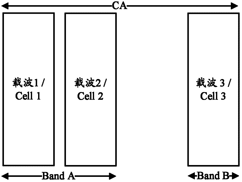
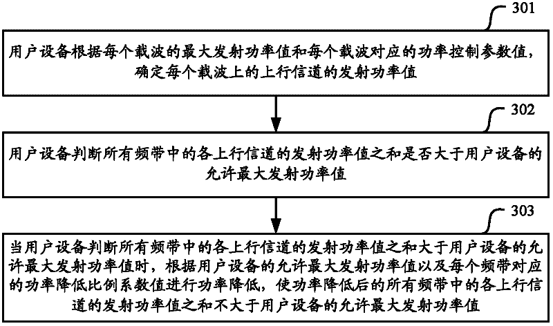
[0064]For the scenario of inter-band CA, there is no uplink power control scheme. In the embodiment of the present invention, the user equipment determines the transmission power value of the uplink channel on each carrier, and judges the transmission power value of each uplink channel in all frequency bands. Whether the sum is greater than the allowable maximum transmit power value of the user equipment, when it is judged that the sum of the transmit power values ​​of the uplink channels in all frequency bands is greater than the allowable maximum transmit power value of the user equipment, according to the allowable maximum transmit power value of the user equipment and each The power reduction proportional coefficient value corresponding to the frequency band performs power reduction, so that the sum of the transmission power values ​​of the uplink channels in all the frequency bands after power reduction is not greater than the allowable maximum transmission power value of t...


PUM


Abstract

The embodiment of the invention relates to the technical field of wireless communication, particularly relates to a method and a device of the uplink power control, used for realizing the uplink power control of UE (user equipment) in a scene of inter-band CA. The method provided by the embodiment of the invention comprises the following steps: determining a transmitting power value of an uplink channel of each carrier wave by the user equipment; when the sum of the transmitting power values of all the uplink channels in all frequency bands is larger than the maximum transmitting power value allowed by the user equipment, reducing the power according to the maximum transmitting power value allowed by the user equipment and a power reduction proportionality factor corresponding to each frequency band so that the sum of the reduced transmitting power values of all uplink channels in all the frequency bands is not larger than the maximum transmitting power value allowed by the user equipment. The uplink power control of the UE can be realized in the scene of inter-band CA by adopting the method and the device provided by the embodiment of the invention.

Description

technical field [0001] The present invention relates to the technical field of wireless communication, in particular to a method and equipment for uplink power control. Background technique [0002] The LTE-A (Long Term Evolution-Advanced, upgraded long-term evolution) system introduces the CA (Carrier Aggregation, carrier aggregation) technology, such as figure 1 As shown, this technology is to aggregate some spectrum allocated to the existing system to form a large bandwidth. At this time, the uplink and downlink carriers in the system can be configured asymmetrically, that is, users may occupy N≥1 carriers for downlink transmission. M≥1 carriers perform uplink transmission. [0003] Carrier aggregation technology enables the terminal to work simultaneously on multiple cells (cells). For an FDD (Frequency Division Duplex, frequency division duplex) system, a cell includes a DL CC (Downlink Component Carrier, downlink component carrier) and a UL CC (Uplink Component Carri...

Claims


Application Information

Patent Timeline
IPC IPC(8): H04W52/14H04W52/34
Inventor 高雪娟林亚男沈祖康
Owner DATANG MOBILE COMM EQUIP CO LTD
Why Eureka
Try Eureka