
Drainage device
A technology of drainage device and lifting device, which is applied in the direction of electrolytic coating, electrophoretic plating, coating, etc., can solve the problems of ineffective discharge of chemicals, great influence on enterprise cost, and pollution of chemical components, and achieve easy installation, quality improvement, low cost effect
- Summary
- Abstract
- Description
- Claims
- Application Information
AI Technical Summary
Problems solved by technology
Method used
Image

Examples
Embodiment 1
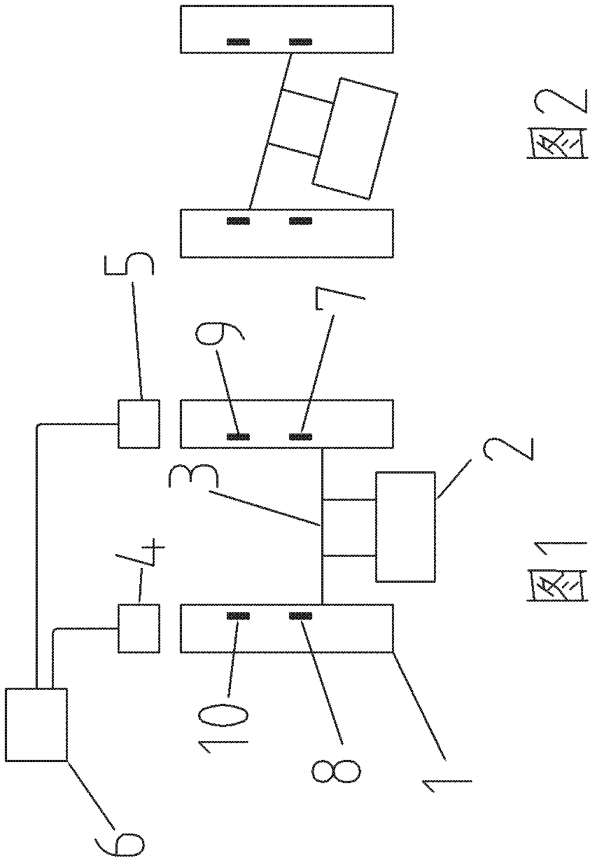
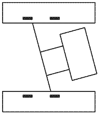
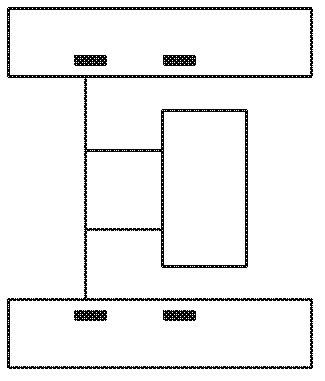
[0017] Such as figure 1 A drainage device shown includes a gantry lifting device body 1, a hanger 2 and a hanger connecting rod 3, the hanger 2 is arranged below the hanger connecting rod 3, and the gantry lifting device body 1 is respectively provided with an independent drive The left motor 4 and the right motor 5, the left motor 4 is connected with the left end of the hanger connecting rod 3 by a chain rope and can drive the left end of the hanger connecting rod 3 to lift, and the right motor 5 is connected with the right end of the hanger connecting rod 3 by a chain rope and can Drive the right end of the hanger connecting rod 3 to go up and down, and the left motor 4 and the right motor 5 are connected with the control unit.
[0018] In this embodiment, the control unit is a PLC controller 6 . The left gantry lifting column of the gantry lifting device body 1 is provided with two upper and lower positioning sensors 8, 10 for detecting the position of the left end of the ...
PUM
 Abstract
Description
Claims
Application Information