
Washing structure of dish washer
A technology for dishwashers and water cups, which is applied to tableware washing machines/rinsing machines, tableware washing machines/rinsing and rinsing machine parts, cleaning equipment, etc. It can solve problems such as unfavorable tableware cleaning, achieve strong washing, save power, The effect of improving the cleaning rate
- Summary
- Abstract
- Description
- Claims
- Application Information
AI Technical Summary
Problems solved by technology
Method used
Image

Examples
Embodiment Construction
[0021] The present invention will be further described below in conjunction with accompanying drawing.
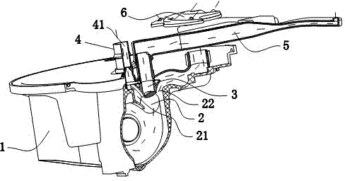
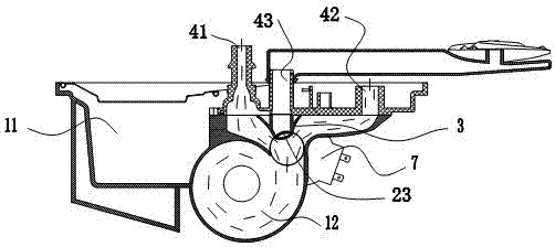
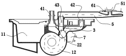
[0022] Such as Figures 1 to 9 As shown, a washing structure of a dishwasher is characterized in that it includes a water cup 1, a paddle 2, a diverter 3, a spray arm seat 4, an inner water pipe 5, a nozzle 6 and a motor 7; wherein the motor 7 is installed On the outer wall of the water cup 1; the spray arm seat 4 is installed on the water cup 1, and the spray arm seat 4 is provided with a first water outlet channel 41, a second water outlet channel 42 and a third water outlet channel 43 isolated from each other; The part 3 is installed in the groove of the water cup 1 and pressed down on the water cup 1 by the spray arm seat 4, and the diverter part 3 cooperates with the inner wall of the water cup 1 to form a first water inlet 21, a second water inlet 22 and a third water inlet which are isolated from each other. The water inlet 23, the first water inlet 21 communicates ...
PUM
 Abstract
Description
Claims
Application Information