Wide dynamic range radio frequency power detection apparatus and detection mode thereof

A wide dynamic range, RF power technology, used in transmission monitoring, electrical components, transmission systems, etc., can solve the problems of slow system output response and long stabilization time

Active Publication Date: 2014-04-02
南京美辰微电子有限公司
View PDF5 Cites 0 Cited by
  • Summary
  • Abstract
  • Description
  • Claims
  • Application Information

AI Technical Summary

Problems solved by technology

At present, detectors can be divided into two categories: logarithmic detectors and root-mean-square power detectors, but the former responds to the amplitude of the input signal, so the output of the input signal with the same power but different modulation methods will be different. ; The latter responds to the power of the input signal, and is more accurate for the power control of the radio frequency system, but the implementation of the traditional RMS converter is as follows: figure 1 As shown, the input signal is sent to the output buffer after being processed by the square unit, the output filter is averaged, and the output of the buffer is fed back to the square unit, so the output of the square unit is / Vout, since the output buffer is a unity gain amplifier, Vout= , the output varies linearly with the root mean square value of the input signal. This structure has three disadvantages: First, because this structure is a closed-loop system, Cave is used to filter the output of the average square unit, and the value is generally several hundred pF to nF, so the stabilization time of the whole loop is longer, and the output response of the system is slower; two, because The / Vout characteristic is achieved by feeding back the output to the square unit to adjust the internal bias current, but the square unit requires an appropriate bias current when it works at high frequencies, so this structure is limited to low-frequency signal applications; 3. The output follows the input signal The RMS value changes linearly, and its input dynamic range changes less with the logarithmic change of the RMS value of the input signal. Therefore, due to the matching problem in the amplification link of the traditional power detector, the input signal of the detector will Overwhelmed by the bias introduced by the matching in the link, the lower limit of the input dynamic range of the detector will be limited

Method used


Image

  • Wide dynamic range radio frequency power detection apparatus and detection mode thereof
  • Wide dynamic range radio frequency power detection apparatus and detection mode thereof
  • Wide dynamic range radio frequency power detection apparatus and detection mode thereof

Examples


Embodiment Construction

[0022] The invention will be described in detail below in conjunction with the drawings and embodiments:

[0023] The present invention proposes a new method and detection device for realizing a wide dynamic range rms power detector, using automatic zeroing to realize mismatch compensation of the internal amplifier circuit of the detector, so as to make the input dynamic range of the rms power detector The lower limit is extended.

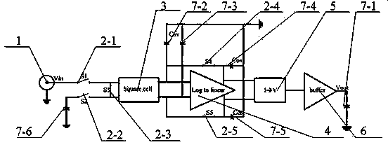
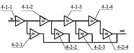
[0024] As a specific embodiment of this patent, the present invention provides an implementation block diagram such as figure 2 Shown is a wide dynamic range radio frequency power detection device, including signal input ports 1, 5 switches, squaring unit 3, logarithmic converter 4, current-voltage converter 5, buffer 6 and 6 capacitors. The converter 4 includes amplifiers and detectors, the number of amplifiers is 2-8, and the number of detectors is 2-8. This patent can use a logarithmic converter with built-in amplifiers and detectors to process the ...


PUM


Abstract

The invention provides a wide dynamic range radio frequency power detection apparatus and a detection mode thereof. The detection apparatus comprises: a signal input port, five switches, a square unit, a logarithmic converter, a current-to-voltage converter, a buffer and six capacitors. The invention provides a novel method for realizing a root-mean-square power detector of a wide dynamic range and a detection apparatus. Automatic zero calibration is utilized to realize mismatching compensation of an amplification circuit inside the detector; therefore, an input dynamic range lower limit of the root-mean-square power detector can be expanded and the input signal range lower limit can even be expanded to -55dBm.

Description

Technical field [0001] The invention relates to the field of wide dynamic range radio frequency power detection, in particular to a wide dynamic range radio frequency power detection device and its detection method. Background technique [0002] Power detectors are widely used in wireless communication systems. They can be applied to the transmission power control of multiple communication standards such as GSM / EDGE, CDMA, LTE, etc., and can also be used for handheld radio frequency signal power measurement. Due to the root mean square power detector The output changes linearly with the rms voltage of the input AC signal, and has nothing to do with the modulation method of the input signal. Therefore, for the radio frequency communication system, a power detector with a wide dynamic range helps the system work better. The current detectors can be divided into two categories: logarithmic detectors and root mean square power detectors, but the former responds to the amplitude of th...

Claims


Application Information

Patent Timeline
Patent Type & Authority Patents(China)
IPC IPC(8): H04B17/00H04B17/327
Inventor 邹闽中曹正军
Owner 南京美辰微电子有限公司
Why Eureka
Try Eureka