Laser ultrasonic thickness measuring method and laser ultrasonic thickness measuring device capable of being used for field detection

A laser ultrasonic and on-site detection technology, applied in measuring devices, using ultrasonic/sonic/infrasonic waves, instruments, etc., can solve the problems of increased device testing flexibility, inappropriate on-site testing, and high laser cost, achieving simple structure, low cost, Portable effect

Active Publication Date: 2012-06-20
启东市荣宇机械有限公司
View PDF8 Cites 23 Cited by
  • Summary
  • Abstract
  • Description
  • Claims
  • Application Information

AI Technical Summary

Problems solved by technology

Patent No. CN00809253.2 provides a laser ultrasonic detection method for detecting high-temperature pipelines, using two lasers, one is used to generate ultrasound propagating in the pipe wall at a specific generation point on the surface of the pipe, The other is coupled with an interferometer to detect the ultrasonic echo generated at a detection

Method used


Image

  • Laser ultrasonic thickness measuring method and laser ultrasonic thickness measuring device capable of being used for field detection
  • Laser ultrasonic thickness measuring method and laser ultrasonic thickness measuring device capable of being used for field detection

Examples


Embodiment Construction

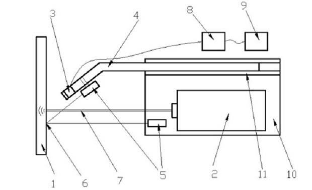
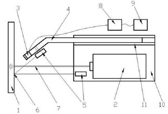
[0015] Such as figure 1 The laser ultrasonic thickness measuring device shown is mainly composed of a laser 2 , a main support 10 , an air-coupled sensor 3 , a support rod 4 , a centering device 5 , a signal processing system 8 and a display system 9 . The laser 2 and the transmission rod 4 are installed on the main support, and a guide rail 11 parallel to the laser beam is arranged on the main support. The rear end of the support rod 4 is installed on the guide rail 11 and can slide back and forth on the guide rail. An air-coupled sensor 3 is arranged at the front end of the rod 4 . The centering device is composed of two small lasers, one is arranged on the pole 4, and its light direction is parallel to the direction in which the air-coupled sensor 3 receives the signal, and the other is arranged on the main support 10, and its light direction is in line with the direction in which the laser emits laser light. direction parallel. The signal processing system 8 is connecte...


PUM


Abstract

The invention discloses a laser ultrasonic thickness measuring method and a laser ultrasonic thickness measuring device capable of being used for field detection. The laser ultrasonic thickness measuring method is characterized in that a laser beam is sent out by a laser to excite an ultrasonic wave on the surface in a specific position of a measured object; meanwhile, an excited wave signal and an echo wave signal produced on the surface in the position are received by an air coupling sensor on the same side of the measured object as the laser; and the propagation distance of the ultrasonic wave is calculated according to the time difference between the excited wave signal and the echo wave signal, and a longitudinal wave propagation velocity of the measured object, so that thickness measurement of the specific position is realized. The device mainly comprises the laser, a main supporting seat, the air coupling sensor, a supporting rod, a centering device, a signal processing system and a display system. The device has a simple and light structure, and can meet the requirements of field detection; and through the adoption of the non-contact type detection method, the thicknesses of high temperature and high-corrosive measured objects can be measured.

Description

technical field [0001] The invention relates to a laser ultrasonic thickness measuring method and device for on-site detection, and the method and device belong to the field of non-destructive testing. technical background [0002] Ordinary ultrasonic thickness gauges need to directly contact the probe on the surface of the measured object with smeared body and couplant for thickness measurement, but the probe used cannot contact the measured object with high temperature or highly corrosive materials. In chemical plants or other enterprises using pressure vessels, containers and some pipelines will generate high heat during operation, which cannot be detected by ordinary contact probes, and the detection of on-site pipelines and equipment arrangements is complicated, due to the narrow space, In the case of a high detection position, the detection staff cannot approach the object to be measured. For the occurrence of the above situation, it is necessary to use non-contact de...

Claims


Application Information

Patent Timeline
IPC IPC(8): G01B17/02
Inventor 姜银方郭镇宁黄宇
Owner 启东市荣宇机械有限公司
Why Eureka
Try Eureka