Iron-copper microelectrolysis reaction tank and preparation method for copperized iron wire net plate

A micro-electrolysis and reaction tank technology, applied in chemical instruments and methods, water/sludge/sewage treatment, water/sewage treatment, etc. The effect of improving biodegradability and improving reaction efficiency

Active Publication Date: 2013-11-06
SHANDONG UNIV
View PDF6 Cites 0 Cited by
  • Summary
  • Abstract
  • Description
  • Claims
  • Application Information

AI Technical Summary

Problems solved by technology

However, the existing iron-carbon micro-electrolysis process has exposed the following problems during operation: iron filings packing compaction and packing bed channeling. After the iron-carbon micro-electrolysis method has been in operation for a period of time, sewage will be generated in the packing after the iron filings packing is agglomerated. Ditching, making the effluent water quality worse
And the iron-carbon micro-electrolysis reaction is generally carried out under acidic conditions, which limits its scope of application to a certain extent.

Method used


Image

  • Iron-copper microelectrolysis reaction tank and preparation method for copperized iron wire net plate
  • Iron-copper microelectrolysis reaction tank and preparation method for copperized iron wire net plate
  • Iron-copper microelectrolysis reaction tank and preparation method for copperized iron wire net plate

Examples


Embodiment 1

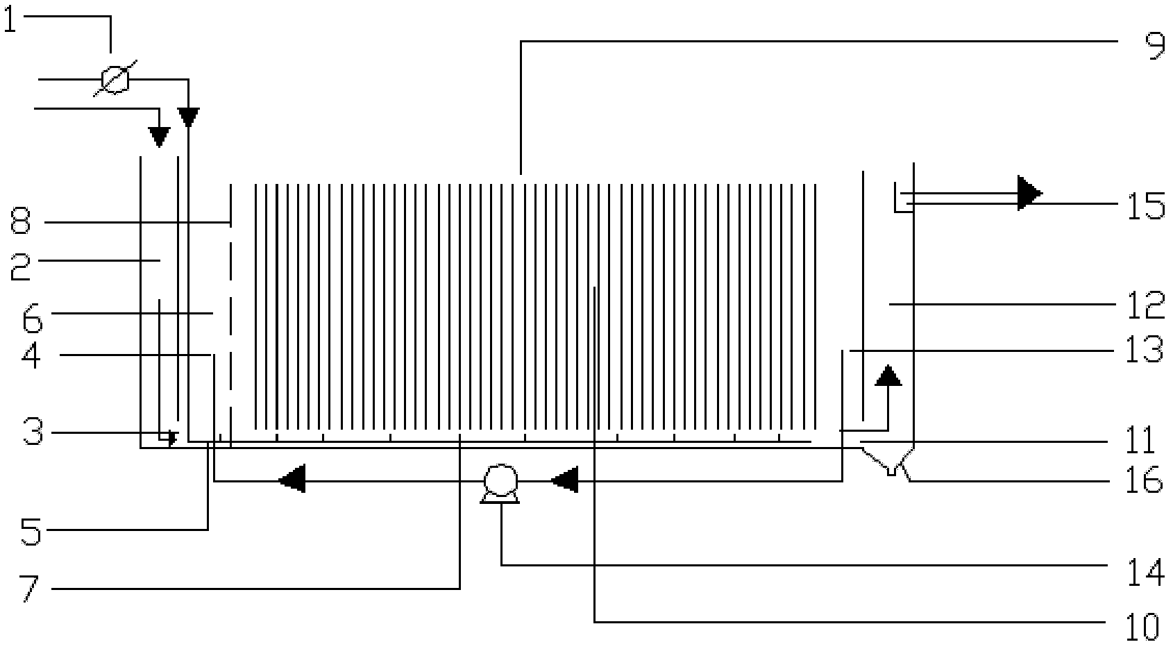
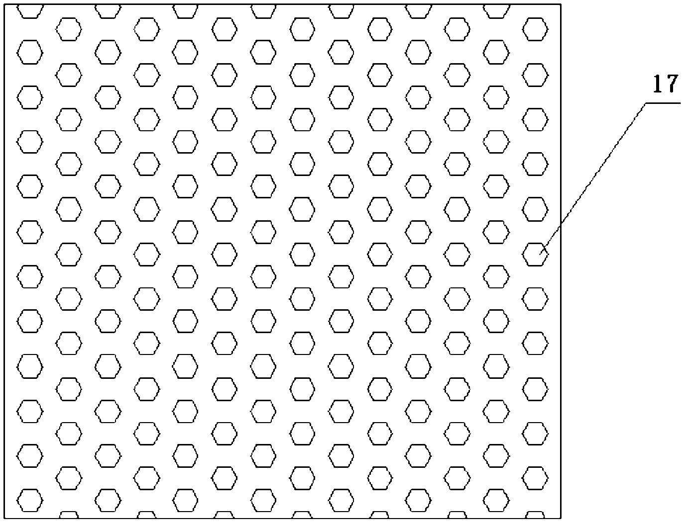
[0035] structured as figure 1 As shown, the iron-copper micro-electrolysis reaction tank of the present invention includes a tank body, and a water inlet chamber 2 and a water outlet chamber 12 are respectively arranged at opposite ends of the tank body, and a micro The electrolytic reaction device is provided with a water distribution buffer plate 8 between the water inlet chamber 2 and the micro-electrolysis reaction device, and the water distribution buffer plate 8 is provided with water distribution holes 17, and the water distribution holes 17 are evenly distributed on the water distribution buffer plate 8, The shape of water distribution hole 17 is preferably hexagonal, and the structure is as image 3shown. The area between the water inlet chamber 2 and the water distribution buffer plate 8 is the water distribution area 6, the water inlet chamber 2 communicates with the water distribution area 6 through the water inlet 3 arranged at the bottom of the water inlet chamb...

Embodiment 2

[0046] The structure of the iron-copper micro-electrolysis reaction tank is as described in Example 1, and the difference is:

[0047] There are 80 copper-plated wire mesh panels 9, and the distance between two adjacent copper-plated wire mesh panels 9 is 0.6cm. The size of the copper-plated wire mesh panels 9 is 65cm×40cm, and there are dense wire mesh holes on the copper-plated wire mesh panels. , The size of the wire mesh hole is 0.8cm×0.8cm.


PUM


Abstract

The invention relates to an iron-copper microelectrolysis reaction tank and a preparation method for a copperized iron wire net plate. Both ends of a tank body of the iron-copper microelectrolysis reaction tank are provided with a water inlet chamber and a water outlet chamber, a microelectrolysis reactor is arranged between the water inlet chamber and the water outlet chamber, sewage enters a water distribution area from the water inlet chamber via a water inlet and then the microelectrolysis reactor via a water distribution buffer plate, and is electrolyzed, the microelectrolysis reactor comprises a plurality of parallel copperized iron wire net plates, and both opposite edges of each copperized iron wire net plate are respectively arranged on both opposite sidewalls of the tank body. The electrolyzed sewage overflows a water outlet weir of the water outlet chamber. The structure of the iron-copper microelectrolysis reaction tank is simple, the applicable water quality range is wide, the cost is low, the service life is long, the chroma, toxicity and CODCr of organic waterwater can be effectively decreased, and the biodegradability of sewage can be enhanced. Copper can be firmly attached on the surfaces of the iron wire nets, and cannot easily come off, and low cost and low energy consumption are truly realized in the process of sewage treatment.

Description

technical field [0001] The invention relates to a preparation method of an iron-copper micro-electrolysis reaction tank and a copper-plated wire mesh board, belonging to the field of sewage treatment. Background technique [0002] 2 After the 1950s, due to the development of the modern chemical industry, a large number of artificially synthesized organic compounds, such as synthetic plastics, synthetic fibers, organic pesticides, synthetic rubber, surfactants, etc., will be produced in large quantities during the production and use of these organic compounds According to the "National Environmental Statistical Bulletin", by the end of 2008, among the total wastewater discharge in China, the industrial organic wastewater accounted for 44.3%. The pollutants in the wastewater are complex and contain a variety of toxic substances. , the concentration is high, and it often contains many refractory organic substances, such as nitroaromatic compounds, polycyclic aromatic hydrocarbo...

Claims


Application Information

Patent Timeline
Patent Type & Authority Patents(China)
IPC IPC(8): C02F1/461
Inventor 岳钦艳张晓伟吴苏清高悦王勃岳东亭高宝玉
Owner SHANDONG UNIV
Why Eureka
Try Eureka