Transmission method of optical fiber transmission subsystem

A technology of optical fiber transmission and transmission method, applied in the transmission field of transmission platform and optical fiber transmission subsystem, can solve the problems of incompatibility of various rates and business functions, business interruption, consumption of optical fiber and cable resources, etc., and achieve flexible system configuration capabilities and logic control functions, reducing unit power consumption, and the effect of low overall cost

Inactive Publication Date: 2012-07-04
上海鼎频通信技术有限公司
View PDF2 Cites 5 Cited by
  • Summary
  • Abstract
  • Description
  • Claims
  • Application Information

AI Technical Summary

Problems solved by technology

[0002] The common transmission platform in the existing computer room adopts a 300pin optical module design, which has poor integration and high power consumption
Various rates and business functions are not compatible
Each additional function or rate requires multiple sets of equipment to be used together, which increases the cost and reduces the overall stability of the system
Moreover, adding a function or rate requires hardware updates and upgrades, consuming a lot o

Method used


Image

  • Transmission method of optical fiber transmission subsystem
  • Transmission method of optical fiber transmission subsystem
  • Transmission method of optical fiber transmission subsystem

Examples


Embodiment 1

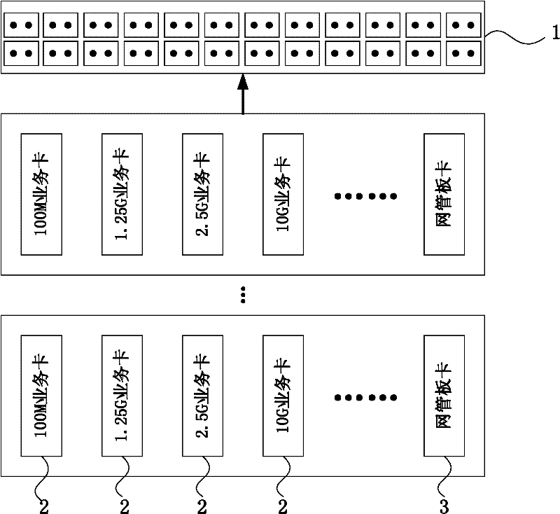
[0026] This embodiment provides an optical fiber transmission subsystem, its external structure is as follows figure 1 As shown, it includes several service cards 2 of different rates, such as 100M service card, 1.25G service card, 2.5G service card, 10G service card, and a network management board 3; the optical fiber transmission subsystem also includes a device frame , the equipment frame provides a rear panel, a front panel, and N card slots; wherein the network management card 3 needs to occupy a slot, and the service card 2 can choose any one of the slots 1 to N; the existing equipment The value of N is 16, and N can also take different integer values ​​according to actual needs. The optical fiber transmission subsystem adopts a front-mounted monitoring and a rear-mounted outlet mode, and the front panel is provided with a network monitoring interface, an Ethernet interface, an optical fiber interface, and an equipment test port; the rear panel is provided with a power i...

Embodiment 2

[0032] This embodiment provides a transmission method for the optical fiber transmission subsystem described in Embodiment 1, and the method includes the following steps:

[0033] Step 1, the several service cards of different rates respectively receive signals of different rates from different customers;

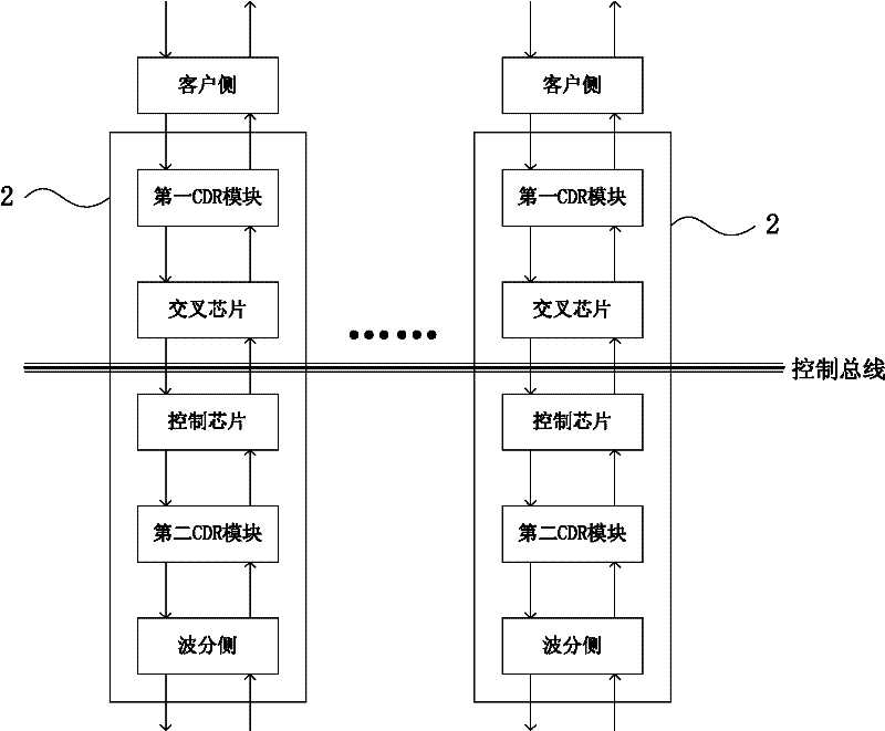
[0034] Step 2, the several service cards of different rates are all connected to the control bus to realize the communication control between the service cards of different rates and the corresponding rate clients; the communication process between the service cards of different rates and the corresponding rate clients is: The first CDR module receives a signal from the client side, the crossover chip transmits the signal from the first CDR module to the control chip, and the control chip transmits the control signal to the second CDR module, and the second CDR module transmits the signal to the control chip. The signal from the control chip is transmitted to the WDM side f...


PUM


Abstract

The invention discloses a transmission method of an optical fiber transmission subsystem. The optical fiber transmission subsystem comprises an equipment machine frame, a plurality of service cards and a webmaster board. The service cards with different rates are managed by the webmaster board. The equipment machine frame is provided with N board slots, wherein one of slot positions is occupied by the webmaster board, and any one of the 1-N slot positions is selected by each service card. The transmission method comprises the following steps of: step 1, respectively receiving signals with different rates from different clients by the service cards with the different rates; step 2, realizing communication control of the service cards with the different rates with the clients with the corresponding rate under the condition that the service cards with the different rates are connected with a control bus. According to the transmission method disclosed by the invention, services with the different rates of 100 M, 1.25 G and 2.5 G are compatible with the subsystem simultaneously, and the service with a rate of 10 G can be further expanded. Therefore, the conventional equipment is used to the greatest extent, the entire cost is lower, the smooth transfer between a novel system and a traditional system is realized, and the transmission method has the advantages of flexible system configuration capability and logic control function.

Description

technical field [0001] The invention belongs to the technical field of communication, and relates to a transmission platform, in particular to a transmission method of an optical fiber transmission subsystem. Background technique [0002] The common transmission platform in the existing computer room uses a 300pin optical module design, which has poor integration and high power consumption. Various rates and business functions are not compatible. Each additional function or rate requires multiple sets of equipment to be used together, which increases the cost and reduces the overall stability of the system. Moreover, adding a function or rate requires hardware updates and upgrades, consuming a lot of optical fiber and cable resources and rack resources in telecommunications equipment rooms. In the process of upgrading, it is necessary to change the original working method, replace hardware and software, cause business interruption, data loss may occur, and project implemen...

Claims


Application Information

Patent Timeline
IPC IPC(8): H04B10/12H04B10/25
Inventor 魏宏刚陈晖李登伸
Owner 上海鼎频通信技术有限公司
Why Eureka
Try Eureka