
Locking devices for injection molding machines and corresponding injection molding machines
A technology of an injection molding machine and a locking device, applied in the field of locking devices, can solve the problems such as long distance from the locking device and high cost of the driving unit
- Summary
- Abstract
- Description
- Claims
- Application Information
AI Technical Summary
Problems solved by technology
Method used
Image

Examples
Embodiment Construction
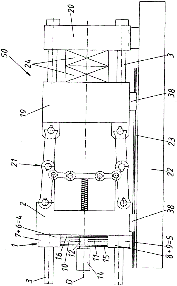
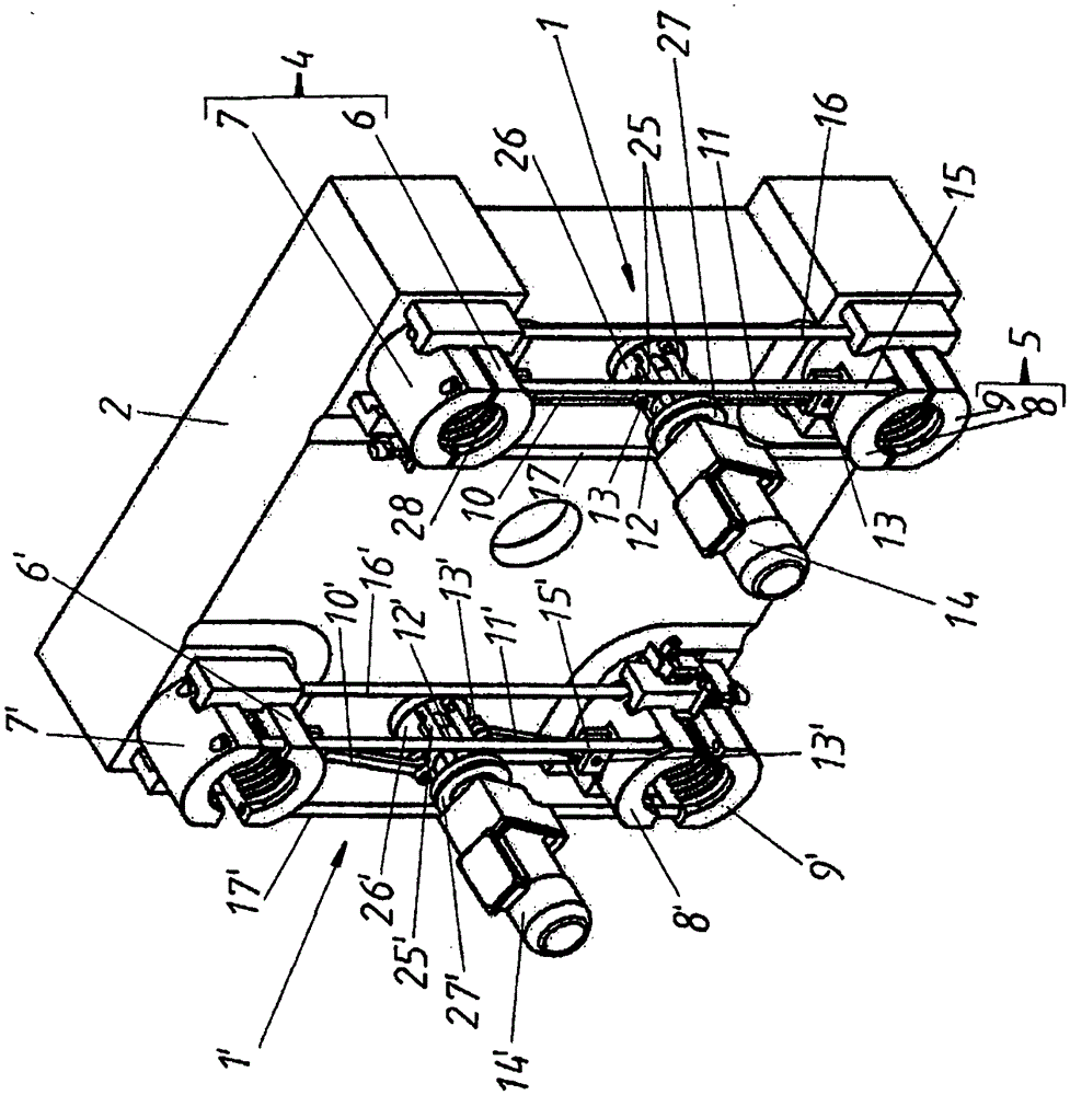
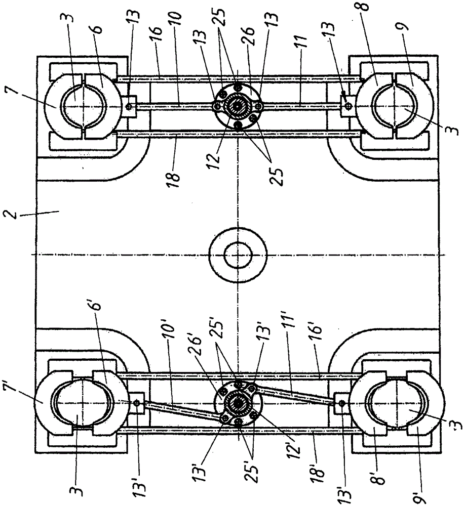
[0027] figure 1 Overall, a view of an injection molding machine 50 is shown, comprising a mold half 24 clamped between a stationary mold clamping plate 20 and a movable mold clamping plate 19 . A crank mechanism 21 is arranged between the movable mold clamping plate 19 and the end plate 2 . The movable mold clamping plate 19 and the end plate 2 are each mounted movably via slides 38 on guide rails 23 of the frame 22 of the injection molding machine 50 . All three plates 2 , 19 and 20 are passed through by a total of four crossbeams 3 , wherein the locking device 1 is shown schematically at the end of the crossbeams 3 on the plate side. This locking device 1 is mounted on the end plate 2 and holds the end plate 2 fixedly on the beam 3 by clamping together the half shells 7 and 6 or 8 and 9 of the clamping elements 4 or 5 . In order to be able to synchronize the two clamping elements 4 and 5, on the one hand the known per se rods 16 and 15 (as well as the connecting rods 17 an...
PUM
 Abstract
Description
Claims
Application Information