Two-way multifunctional electromagnetic valve

A solenoid valve and multi-functional technology, applied in the field of solenoid valves, can solve problems such as high pull-in voltage, slow response, and system failure, and meet the requirements of small dynamic pressure changes, lower technical level, and shorten electromagnetic response time Effect

Inactive Publication Date: 2012-07-18
WUHAN DONGJIANG FEITE SCI & TECH CO LTD
View PDF6 Cites 8 Cited by
  • Summary
  • Abstract
  • Description
  • Claims
  • Application Information

AI Technical Summary

Problems solved by technology

[0002] Conventional solenoid valves can only respond to DC signals or pulse signals individually
At present, with the implementation of Euro III and Euro IV automobile emission standards, some solenoid valves need to work under the DC signal and some solenoid valves work under the pulse signal, but the receiving power signal is different , multiple sets of solenoid valves with the same appearance and installation dimensions need to be able to be freely assembled according to the vehicle model requirements, and the conventional DC solenoid valves in the prior art cannot meet this requirement
[0003] The medium inlet and outlet of conventional solenoid valves cannot be interchanged, and it is easy to cause the system to not work properly after the medium inlet and outlet are reversed during the installation process, which requires high responsibility for the assembly personnel.
Moreover, conventional solenoid valves can only be adapted to gas medium or liquid medium alone, and cannot meet the requirements of the versatility of solenoid valves.
[0004] Ordinary solenoid valves have a large product volume, a large amount of enameled wire, slow response, high pull-in voltage and large power loss, resulting in an increase in product cost

Method used


Image

  • Two-way multifunctional electromagnetic valve
  • Two-way multifunctional electromagnetic valve
  • Two-way multifunctional electromagnetic valve

Examples


Embodiment Construction

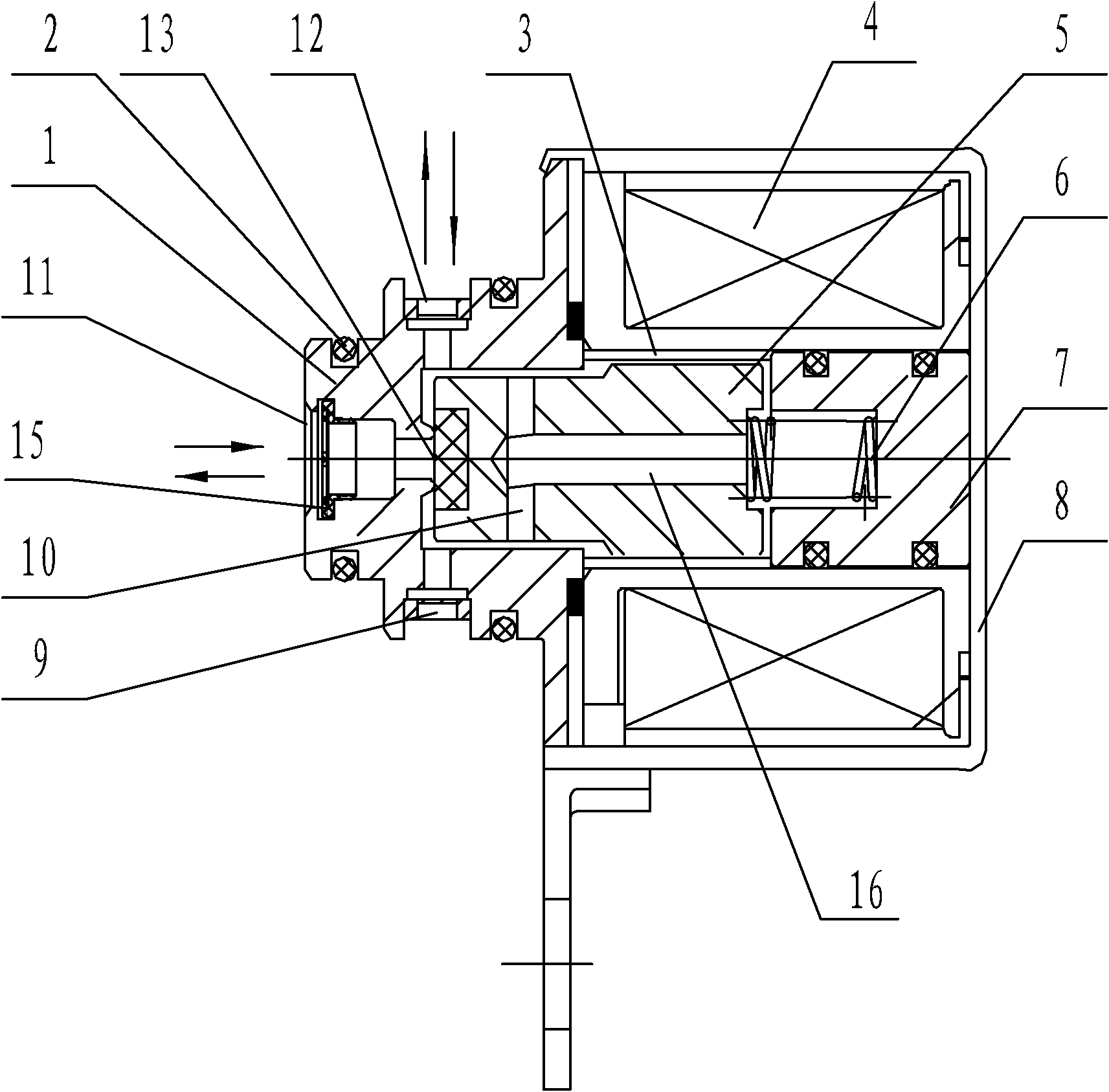
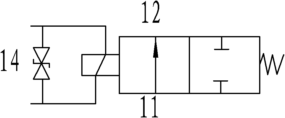
[0025] like figure 1 , figure 2 As shown, the present invention mainly includes a valve body 1 and an electromagnet part. The valve body 1 is provided with a medium inlet 11 and a medium outlet 12, which can be communicated with the gas / liquid source and the gas / liquid device respectively. The electromagnet part The valve core mainly includes coil 4, static magnetic core 7, and moving magnetic core 5. The coil injection molding assembly is adopted. The valve core is arranged in the coil assembly. TVS tube 14, lead wire and coil are also arranged in the coil injection molding assembly. 4 and the skeleton, the TVS tube 14 is connected in parallel with the coil 4, the lead head is connected and led out from the coil 4, and is fully encapsulated in the coil injection assembly. The setting of the TVS tube can effectively suppress the high voltage at the moment of rapid power failure, reduce the volume of the coil and related parts, shorten the electromagnetic response time, and c...


PUM


Abstract

The invention belongs to a two-way multifunctional electromagnetic valve which comprises a valve body and an electromagnet part. The electromagnet part adopts a coil injection-molding assembly; and a TVS (transient voltage suppressor) pipe is arranged in the coil injection-molding assembly. The valve adopts a valve core structure that springs are embedded in a static magnetic core and a dynamic magnetic core and a structure that the static magnetic core is combined with a metal sleeve, has the structure characteristics that a rubber sealing layer at the front end of the dynamic magnetic core simultaneously separates a medium inlet and a medium outlet of the valve body and the medium inlet and the medium outlet are exchangeable, and is an electromagnetic valve which can simultaneously controlled by a direct current signal and a direct current pulse electric signal and further can be simultaneously applicable to a gas medium or a liquid medium, and the medium inlet and the medium outlet of the valve can be used in an exchangeable way.

Description

technical field [0001] The invention relates to a solenoid valve, in particular to a system that is suitable for automobiles and various types of systems that need to control the opening and closing of gas or liquid paths, including a gas / liquid path control system controlled by an ECU for solenoid valves, and a 0-36V low-voltage power supply system. Solenoid valve working in gas / liquid control system. Background technique [0002] Conventional solenoid valves can only respond to a single DC signal or a pulse signal, respectively. At present, with the implementation of Euro III and Euro IV vehicle emission standards, some solenoid valves need to work under the DC signal, and some solenoid valves work under the pulse signal, but the power supply signal is different. , the multiple sets of solenoid valves with the same appearance and installation size need to be freely assembled according to the requirements of the vehicle model, and the conventional DC solenoid valves in the...

Claims


Application Information

Patent Timeline
Patent Type & Authority Applications(China)
IPC IPC(8): F16K1/00F16K31/06F16K51/00
Inventor 黎昭霞唐玉芬涂志刚朱娅玲
Owner WUHAN DONGJIANG FEITE SCI & TECH CO LTD
Why Eureka
Try Eureka