Production method of optical fiber preset core insert and positioning device

A positioning device and production method technology, applied in the field of optical fiber, can solve the problems of easy damage, lower pass rate, large insertion loss, etc., and achieve the effects of reducing production costs, ensuring alignment, and ensuring pass rate

Active Publication Date: 2012-07-25
WANMA TECH CO LTD
View PDF6 Cites 10 Cited by
  • Summary
  • Abstract
  • Description
  • Claims
  • Application Information

AI Technical Summary

Problems solved by technology

[0003] 1. Since the bare optical fiber has been cut, only a small section (3-5 mm) is exposed from the end face of the ferrule tail after grinding; because the exposed length of the optical fiber is too short to use the optical fiber loss measuring instrument, it is difficult to correct after production. The insertion loss of the ferrule and the minimum value of the insertion loss of each ferrule surface are inspected (if the ferrule surface is unqualified, it cannot be identified by the instrument), which has virtually caused the insertion loss in the production of quick connectors to be too large, which cannot improve the qualified Rate;
[0004] 2. The bare optical fiber itself is relatively fragile, and it is easy to be damaged during production. Once the bare optical fiber in the optical fiber preset ferrule is damaged, it cannot be repaired, resulting in a decrease in the pass rate;
[0006] 4. The aperture of the ceramic ferrule of the optical fiber preset ferrule is larger than the outer diameter of the optical fiber. Manual insertion cannot guarantee the alignment of the optical fiber, and the final cut bare optical fiber surface will form a certain angle.

Method used


Image

  • Production method of optical fiber preset core insert and positioning device
  • Production method of optical fiber preset core insert and positioning device
  • Production method of optical fiber preset core insert and positioning device

Examples


Embodiment Construction

[0037] The present invention will be further described below in conjunction with the accompanying drawings, but the present invention is not limited to the following examples.

[0038] The current conventional production method is to cut the bare optical fiber to a fixed length, and then insert it into the ceramic ferrule for grinding. Due to the short length of the bare optical fiber, the insertion loss and return loss cannot be tested after grinding, so the quality of the product is difficult to control. , The product qualification rate is not high.

[0039] A production method of an optical fiber preset ferrule proposed by the present invention comprises the following steps:

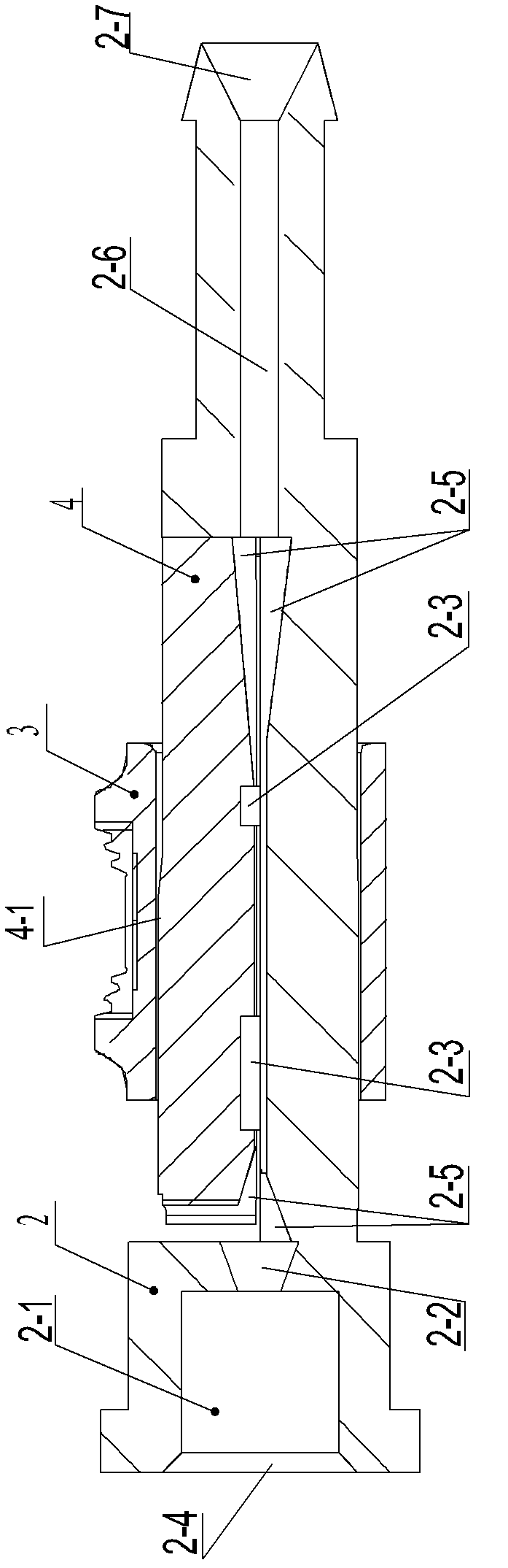
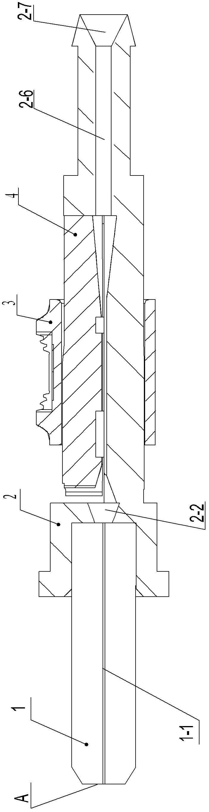
[0040] a. Fix the ceramic ferrule 1 horizontally on the working table of the ferrule grinder;

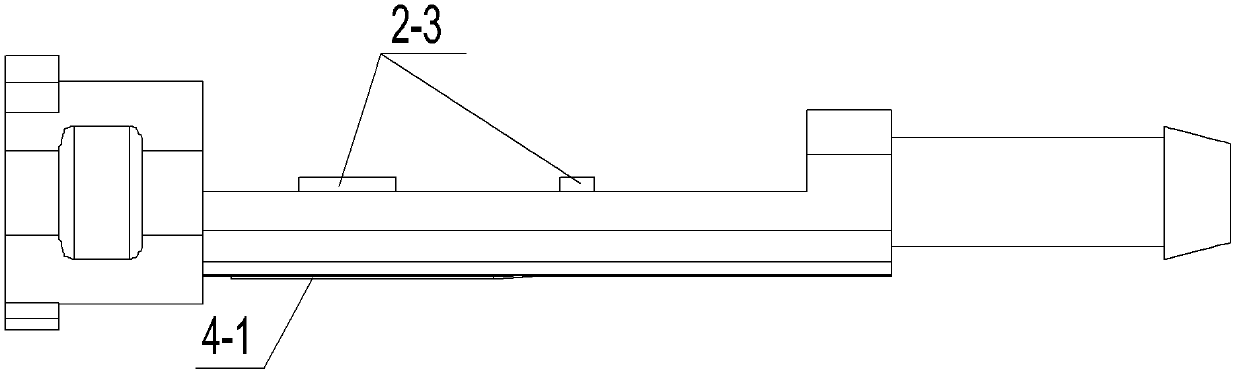
[0041] b. Set a section of protective sleeve on the uncut bare optical fiber, and the end of the bare optical fiber is exposed from the protective sleeve;

[0042] c. Insert the end of the bare fiber hori...


PUM


Abstract

The invention relates to a production method of an optical fiber preset core insert, which has the characteristics that the insertion loss of the optical fiber core insert in the production process can be detected by an instrument. The technical scheme is as follows: the production method of the optical fiber preset core insert is characterized by comprising the following steps: (a) horizontally fixing a ceramic core insert on a workbench of a core insert grinder; (b) sheathing a protective sleeve on a bare optical fiber which is not cut; (c) inserting the bare optical fiber into an optical fiber hole from the tail part of the ceramic core insert; (d) starting the core insert grinder to grind the end surface of the head part of the ceramic core insert and the end surface of the bare optical fiber; (e) conducting return loss test on a light guiding surface; (f) if the test result is disqualified, repeating the steps (d-e) until the test is qualified; and (g) if the test result is qualified, stripping the protective sleeve of the bare optical fiber, and taking the core insert out of the core insert grinder, and preserving a tail fiber with a certain length, and cutting with a cutter.

Description

technical field [0001] The invention relates to the field of optical fiber technology, in particular to a production method for an optical fiber preset ferrule and a positioning device for producing an optical fiber preset ferrule. Background technique [0002] With the rapid expansion of FTTH (fiber-to-the-home) in China, as an indispensable connection device for its terminals, the number of optical fiber quick connectors (or field connectors) is also increasing; As the core component of the optical fiber quick connector, its conventional production process is: first cut the bare optical fiber into a small section, then insert it into the hole in the axial direction of the ferrule and fix it, and then grind the end face of the ferrule head to make the ferrule The end face of the core and the end face of the bare fiber are ground into the same plane (forming a standard light guide surface); the above production method faces the following problems: [0003] 1. Since the bare...

Claims


Application Information

Patent Timeline
Patent Type & Authority Applications(China)
IPC IPC(8): G02B6/38G02B6/36
Inventor 林啸洋徐长鑫黄茹江国强水少青
Owner WANMA TECH CO LTD
Why Eureka
Try Eureka