Hydraulic power unit including centrifugal pump and vane pump in motor

A technology of hydraulic power unit and vane pump, which is applied in the direction of machine/engine, pump, pump device, etc., can solve the problems of high noise of hydraulic power unit, complex hydraulic power unit, insufficient oil absorption, etc., and achieves reliable sealing, compact structure, and elimination of Effects of Aerodynamic Noise and Cavitation Noise

Inactive Publication Date: 2012-08-08
LANZHOU UNIVERSITY OF TECHNOLOGY
View PDF2 Cites 8 Cited by
  • Summary
  • Abstract
  • Description
  • Claims
  • Application Information

AI Technical Summary

Problems solved by technology

In addition, the motor connected to the vane pump generally contains a cooling fan, so the noise of the entire hydraulic power unit is also very large; at the same time, because the vane pump has an overhanging shaft, there is an external leakage path
General hydraulic pumps have the problem of insufficient oil absorption to vary

Method used


Image

  • Hydraulic power unit including centrifugal pump and vane pump in motor
  • Hydraulic power unit including centrifugal pump and vane pump in motor
  • Hydraulic power unit including centrifugal pump and vane pump in motor

Examples


Embodiment Construction

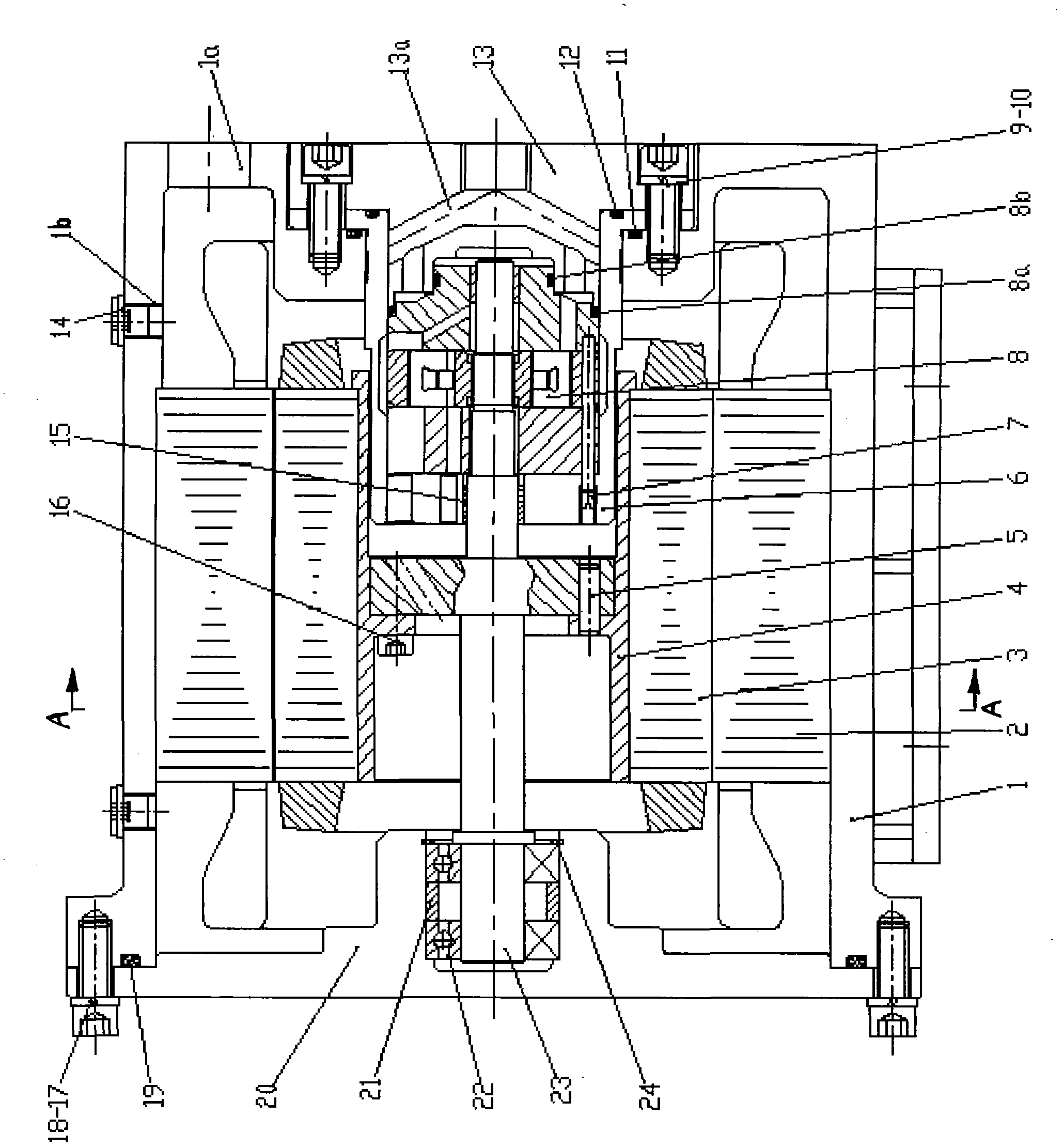
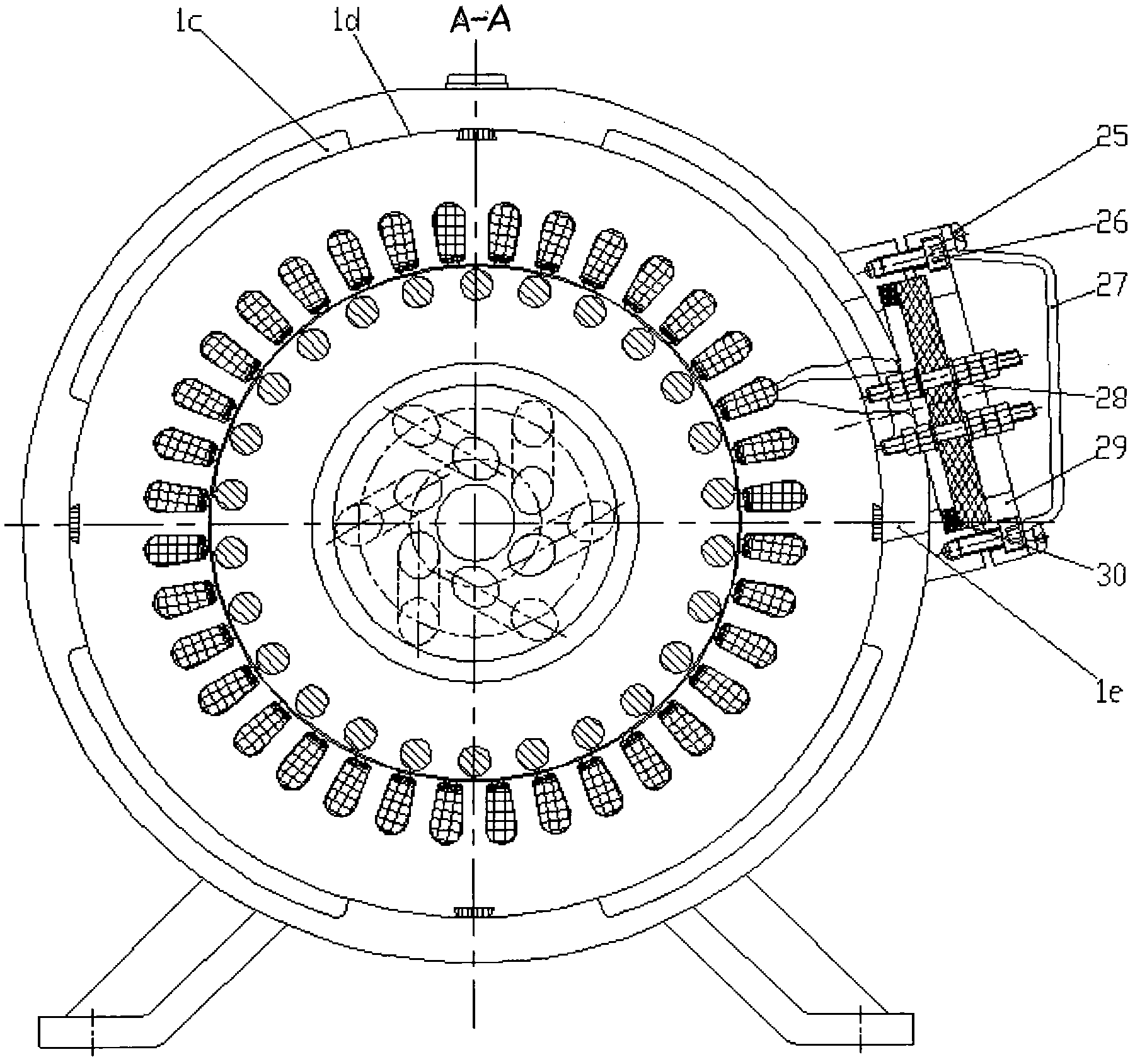
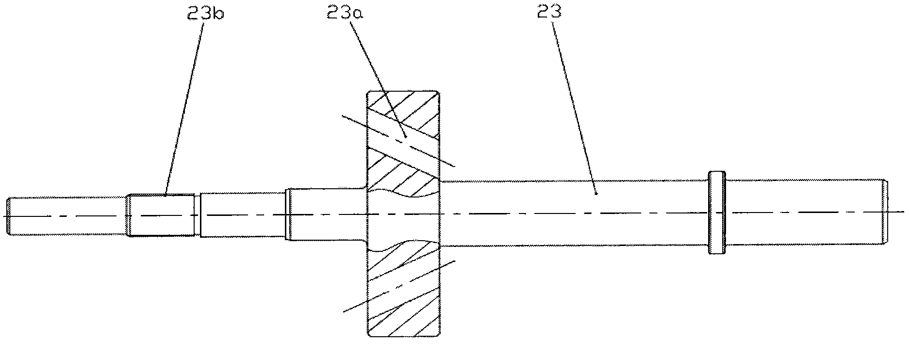
[0009] like Figure 1 to Figure 5 As shown, the present invention is a hydraulic power unit containing a centrifugal pump and a vane pump in a motor, and has a base 1, as well as a motor stator 2, a motor rotor 3, a rotor sleeve 4, a pump core seat 6, and a vane pump 8. The motor rotor 3 and The rotor sleeve 4 and the main shaft 23 are connected to form a rotor body, and are supported on the end cover 20 and the pump core seat 6 through the sliding bearing 15 in the pump core seat 6 and the two sets of rolling bearings 22 in the end cover 20, and the vane pump 8 is splined. 23b is connected to the main shaft 23, the vane pump 8 is installed in the pump core seat 6, and is fixed to the machine through the oil outlet gland 13, the third sealing ring 11, the fourth sealing ring 12, the second screw 9 and the first washer 10. On the base 1, the motor stator 2 is press-fitted on the inner boss 1d on the base 1, the end cover 20 and the fifth sealing ring 19 are fixed on the base 1 ...


PUM


Abstract

The invention provides a hydraulic power unit including a centrifugal pump and a vane pump in a motor. A motor rotor (3) is connected with a rotor sleeve (4) and a spindle (23) to form a rotor body, and is supported on an end cover (20) and a pump core seat (6) by a sliding bearing (15) in the pump core seat (6) and two groups of rolling bearings (22) in the end cover (20); the vane pump (8) is connected with a spindle (23) by a spline (23b), mounted in the pump core seat (6), and fixed on a stand (1) by an oil outlet press cover (13); a motor stator (2) is pressed on a boss (1d) within the stand (1); the end cover (20) and a sealing ring (19) are fixed on the stand (1); an oil outlet of the vane pump (8) is communicated with a runner (13a) of the oil outlet press cover (13) so as to output high pressure oil; power is supplied to the motor in the hydraulic power unit by a wiring terminal (28); and the wiring terminal (28) and a sealing ring (30) are fixed on the stand (1) by a bolt (26) and a press cover (29).

Description

technical field [0001] The invention relates to a hydraulic motor pump power unit, in particular to a hydraulic power unit of a motor vane pump containing a centrifugal pump. Background technique [0002] The hydraulic power unit is the heart of the hydraulic system. At present, the hydraulic power unit with the electric motor as the driving force is a discrete structure. Vane pump is a structural form of hydraulic pump, which has the advantages of good flow uniformity and low noise, so it has been widely used. As an independent hydraulic power element, the vane pump needs to be connected with an independent motor or internal combustion engine through its outrigger pump shaft to form a motor-hydraulic pump unit to form a hydraulic power unit to work. This connection requires couplings, pump frames and other devices. Due to the large volume of the independent motor and the accessories such as couplings, the volume and weight of the entire hydraulic power unit are very large....

Claims


Application Information

Patent Timeline
IPC IPC(8): F04B23/12
Inventor 冀宏王金林孙天健王建森王峥嵘汪翔翎武俊合赵光明
Owner LANZHOU UNIVERSITY OF TECHNOLOGY
Why Eureka
Try Eureka