

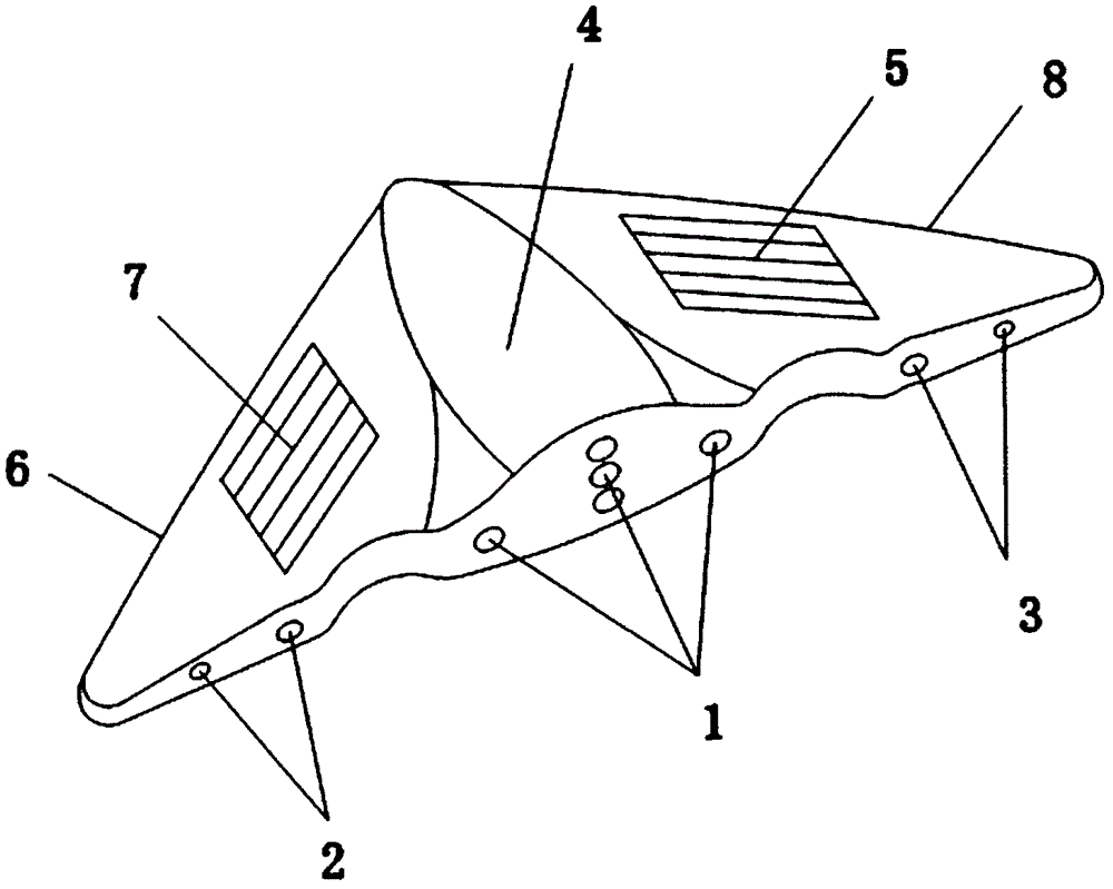
Solar energy speed-reducing turn light
A turn signal and solar energy technology, applied in the direction of optical signals, signal devices, transportation and packaging, etc., can solve problems such as blind spots, accidents, vehicle short circuit, fire and failure, etc., to improve driving safety, variety, The effect of easy installation
- Summary
- Abstract
- Description
- Claims
- Application Information
AI Technical Summary
Problems solved by technology
Method used
Image

Examples
Embodiment 1
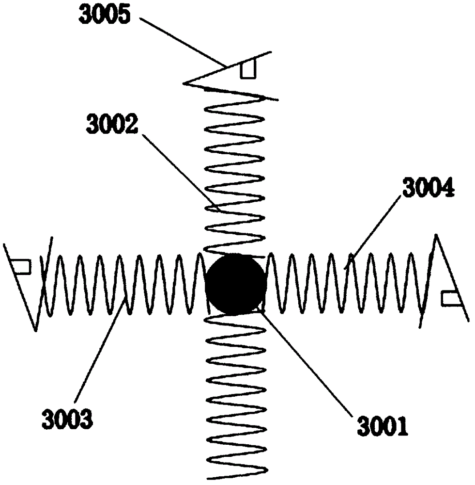
[0027] Embodiment one: if Figure 4 As shown, when the car needs to decelerate while driving, the solid circular steel ball 3001 receives the forward inertial force generated by the deceleration of the car, so that the solid circular steel ball 3001 squeezes the front spring 3002, and the front spring 3002 squeezes the connected sheet pressure switch 3005 and turn on the power supply at the other end of the sheet pressure switch 3005 to realize that the deceleration lamp 1 is always on.
Embodiment 2
[0028] Embodiment two: if Figure 5 As shown, when the car is turning right, the solid circular steel ball 3001 is subjected to the leftward force generated by the car turning right, so that the solid circular steel ball 3001 squeezes the left spring 3003, and the left spring 3003 squeezes the connecting piece Press the switch 3005 and turn on the power supply at the other end of the sheet pressure switch 3005 to realize the left-hand lamp 2 flashing.
Embodiment 3
[0029] Embodiment three: as Image 6 As shown, when the car is turning left, the solid circular steel ball 3001 is subjected to the rightward force generated by the car turning left, so that the solid circular steel ball 3001 squeezes the right spring 3004, and the right spring 3004 squeezes the connecting piece Press the switch 3005 and connect the power supply at the other end of the sheet pressure switch 3005 to realize the flashing of the right direction lamp 2.
PUM
 Abstract
Description
Claims
Application Information