Anti-seismic large deformation expansion device of comb plate

A technology of large deformation and telescopic device, which is applied to bridge parts, bridges, buildings, etc., can solve the problems of not being able to meet the super-strong and extra-large longitudinal and lateral displacement, unable to solve the lateral displacement, and the amount of lateral displacement is small, and achieves simple structure, Convenience of construction and effect of improving service life

Inactive Publication Date: 2014-09-03
SHANGHAI HUICHENG ARCHITECTURE DECORATION +1
View PDF6 Cites 0 Cited by
  • Summary
  • Abstract
  • Description
  • Claims
  • Application Information

AI Technical Summary

Problems solved by technology

[0003] Some comb-tooth plate expansion devices with large deformation have also been developed in China, but they are all expansion devices that solve "two-dimensional deformation". They cannot meet the requirements of extremely strong and large longitudinal and lateral displacements during earthquakes. There are following problems:
[0007] (4) When the plane rotates, the comb teeth of the movable comb plate produce lateral displacement, and the tooth head of the movable tooth plate should push the tooth head of the fixed comb plate to move laterally. In order to prevent the comb teeth of the fixed comb plate from breaking, the fixed comb The combs and steel slats of the tooth plate are connected by vertical pins. The lateral displacement is only the gap between the anchor bolt hole and the screw rod. The lateral displacement is very small and cannot solve the problem of lateral displacement.

Method used


Image

  • Anti-seismic large deformation expansion device of comb plate
  • Anti-seismic large deformation expansion device of comb plate
  • Anti-seismic large deformation expansion device of comb plate

Examples


Embodiment 1

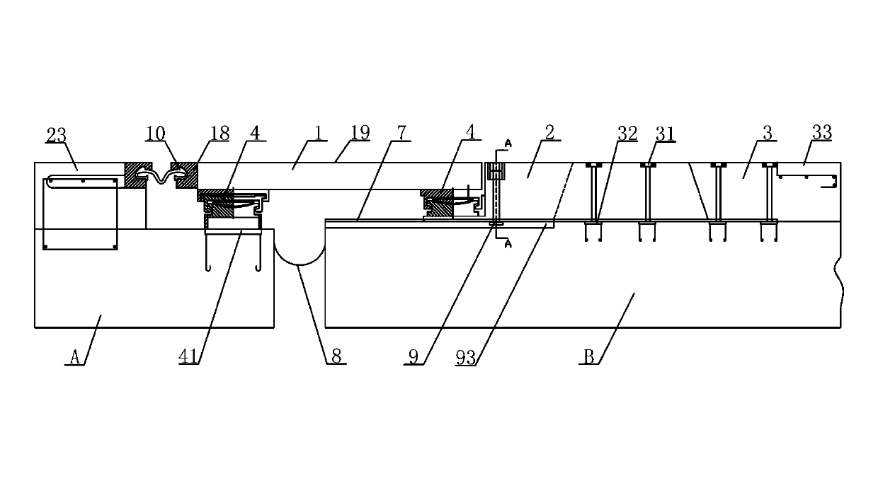
[0024] See attached image 3 ~ attached Figure 5 , the present invention is installed and constructed according to the following steps:

[0025] , Cut and install reserved grooves on the beam body

[0026] Cut the reserved grooves for the installation of beam body A on one side and beam body B on the other side. When excavating concrete, the main reinforcement, stirrups and prestressed pipes in the beam body must not be damaged, and the uncut asphalt concrete must be protected and pre-embedded. For steel bars, ensure the number of pre-embedded steel plates, and make up for any defects in time.

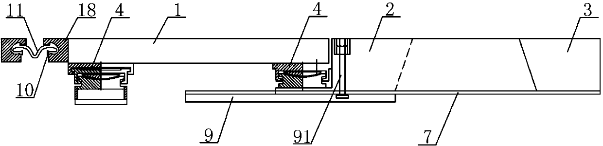
[0027] , Install the spherical bearing

[0028] Determine the positions of two spherical bearings 4 on one side of the beam body A, one of the two spherical bearings 4 adopts one-way tensile resistance, and the other adopts two-way tensile resistance, and it is calculated according to the longitudinal and transverse slope factors of the bridge deck For the different elevations...


PUM


Abstract

The invention discloses an anti-seismic large deformation expansion device of a comb plate. The expansion device is characterized in that a horizontal limiting slippage mechanism is arranged on a comb tooth section of a movable comb plate; a seam crossing plate and a horizontal single-seam deformation unit are arranged at the back end of the movable comb plate; the seam crossing plate is fixedly arranged on spherical supports at two ends, and a spherical support at one end is fixedly arranged on the movable comb plate; the movable comb plate is placed on a stainless steel sliding plate together with comb teeth of a fixed comb plate in a mutual spigot and socket mode; and the movable comb plate is slidingly connected with the stainless steel sliding plate, and the fixed comb plate is fixedly connected with the stainless steel sliding plate. Compared with the prior art, the expansion device is provided with a three-dimensional deformation function which is provided with plane and vertical rotation and horizontal displacement, consistent deformation can be performed along with a bridge structure, not only deformation requirements for daily use are satisfied, but also the deformation requirements due to great longitudinal and horizontal displacement of the bridge when an earthquake happens can also be satisfied, the structure is simple, the construction is convenient, the construction cost is low, and the service life is long.

Description

technical field [0001] The invention relates to the technical field of bridge structures, in particular to an anti-seismic large-deformation comb tooth plate telescopic device. Background technique [0002] At present, China is in a period of vigorous development of modern long-span bridges, and flexible bridges such as long-span suspension bridges and cable-stayed bridges are being built rapidly. Today, we are in a period of high earthquake risk. Earthquakes occur frequently all over the world, and the intensity of earthquakes is getting stronger and stronger, which brings great harm to the people of the world. In order to ensure that the bridge can be used safely, anti-seismic measures are taken for the bridge structure, and as a connecting structure between the bridge spans—the expansion device of the bridge should also consider anti-seismic measures. Only the expansion device of the comb tooth plate has the function of "three-dimensional deformation", and the deformatio...

Claims


Application Information

Patent Timeline
Patent Type & Authority Patents(China)
IPC IPC(8): E01D19/06
Inventor 傅若梁马骉黄桂福翁思熔
Owner SHANGHAI HUICHENG ARCHITECTURE DECORATION
Why Eureka
Try Eureka