Luminous keyboard

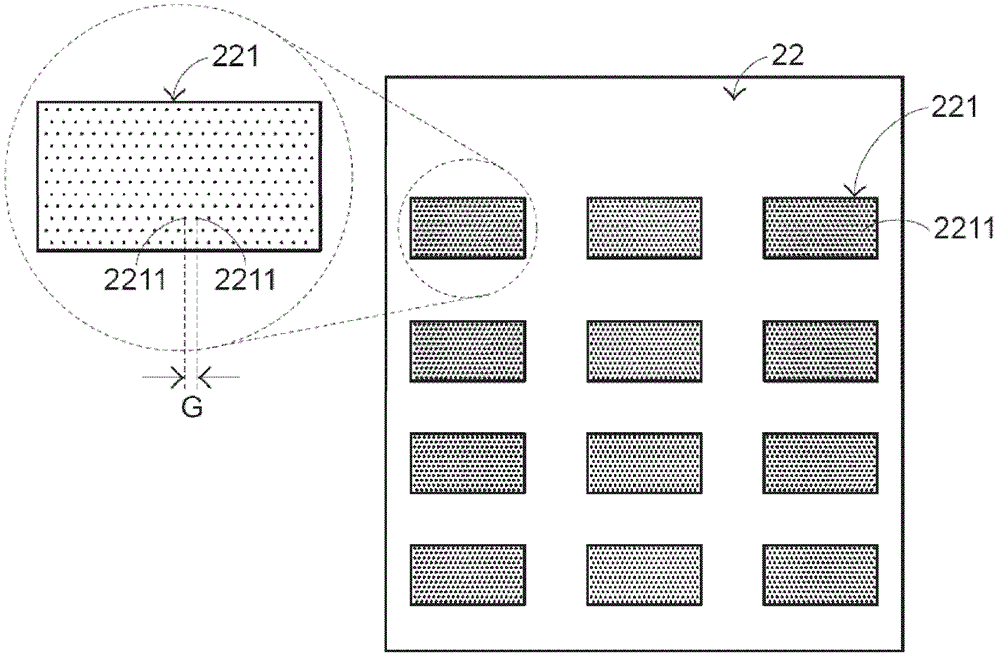
A light-emitting keyboard, light-emitting module technology, applied in electrical components, electrical switches, circuits, etc., can solve the problems of uneven distribution of light guide dots 2211, loss of light guide effect, etc., to ensure lighting effect, good yield, and reduce manufacturing. cost effect

Inactive Publication Date: 2012-11-28
PRIMAX ELECTRONICS LTD
View PDF5 Cites 5 Cited by
  • Summary
  • Abstract
  • Description
  • Claims
  • Application Information

AI Technical Summary

Problems solved by technology

[0008] However, after the existing luminous keyboard 2 has been used for a long time, its multiple keys 20 are often touched and pressed to wear out the multiple light guide grid points 2211 on the light guide plate 222, because there is a gap G between each light guide grid point 2211. , so that the edge area of ​​each light guiding network point 2211 is very likely to be worn out, and the wear situation is particularly serious at the edge of the light guiding area 221, so a plurality of light guiding network points 2211 become unevenly distributed and damage its light guiding effect

Method used


Image

  • Luminous keyboard
  • Luminous keyboard
  • Luminous keyboard

Examples


Embodiment Construction

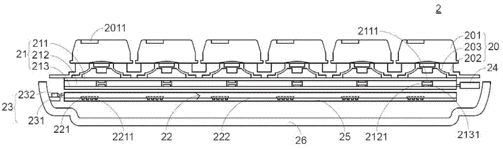
[0029] In view of the defects of the prior art, the present invention provides a luminous keyboard. see Figure 4 , which is a schematic cross-sectional view of the structure of the first preferred embodiment of the light-emitting keyboard of the present invention. The luminous keyboard 3 includes a plurality of keys 30 , a membrane switch circuit 31 , a light guide plate 32 , a light emitting module 33 , a main circuit board 34 , a reflector 35 and a base 36 . The button 30 includes a button cap 301 , a button casing 302 and an elastic body 303 . In the luminous keyboard 3, the above components are arranged in the order of key cap 301, key housing 302, elastic body 303, membrane switch circuit 31, light guide plate 32, reflector 35 and base 36 from top to bottom. One side of the switch circuit 31 , while the main circuit board 34 is located on the other side of the membrane switch circuit 31 . In this preferred embodiment, the luminous keyboard 3 is a keyboard for a deskto...


PUM


Abstract

The invention relates to a luminous keyboard. The luminous keyboard comprises a plurality of keys, a membrane switch circuit and a light emitting module used for generating light beams, wherein the membrane switch circuit is triggered by the keys to generate signals; the membrane switch circuit comprises a plurality of light guide areas; and each light guide area is filled with a light guide layer in a gapless way. Therefore, the light guide layer has a firm structure and is not easy to wear. By using the luminous keyboard, the light emitting effect of the luminous keyboard can be ensured; and moreover, the yield of the light guide layer of the luminous keyboard is high.

Description

technical field [0001] The invention relates to a keyboard, in particular to a luminous keyboard with a luminous function. Background technique [0002] The keyboard is a commonly used computer peripheral device for inputting text or commands to the computer. see figure 1 , which is a schematic diagram of an appearance structure of an existing keyboard. There are a plurality of keys 10 on the surface of the existing keyboard 1, and these keys 10 are classified into general keys 101, number keys 102, and function keys 103, etc. These keys are pressed by the user's fingers to generate corresponding signals to the user. The computer enables the computer to execute the pressed key functions, for example, the general key 101 is used to input symbols such as English letters, the number key 102 is used to input numbers, and the function key 103 is used to provide various functions, such as F1-F12 and so on. [0003] With the evolution of technology, keyboard manufacturers are co...

Claims


Application Information

Patent Timeline
Patent Type & Authority Applications(China)
IPC IPC(8): H01H13/83
Inventor 陈仲渊
Owner PRIMAX ELECTRONICS LTD
Why Eureka
Try Eureka