
Connecting link-cam dual self-locking mechanism
The technology of a link mechanism and a cam is applied in the field of mechanical transmission to achieve the effects of improving the reliability of self-locking, reducing errors and ingenious structure.
Patent Information
- Authority / Receiving Office
- CN · China
- Patent Type
- Patents(China)
- Current Assignee / Owner
- Publication Date
- 2014-07-30
Smart Images
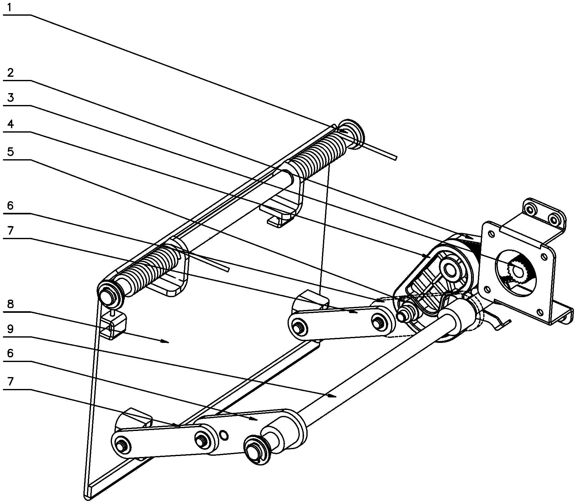
Figure 1 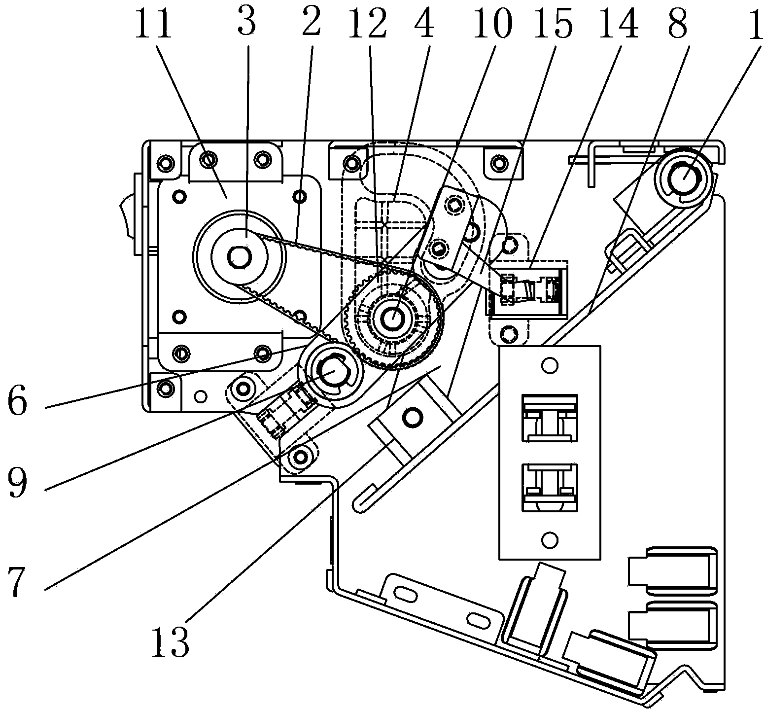
Figure 2 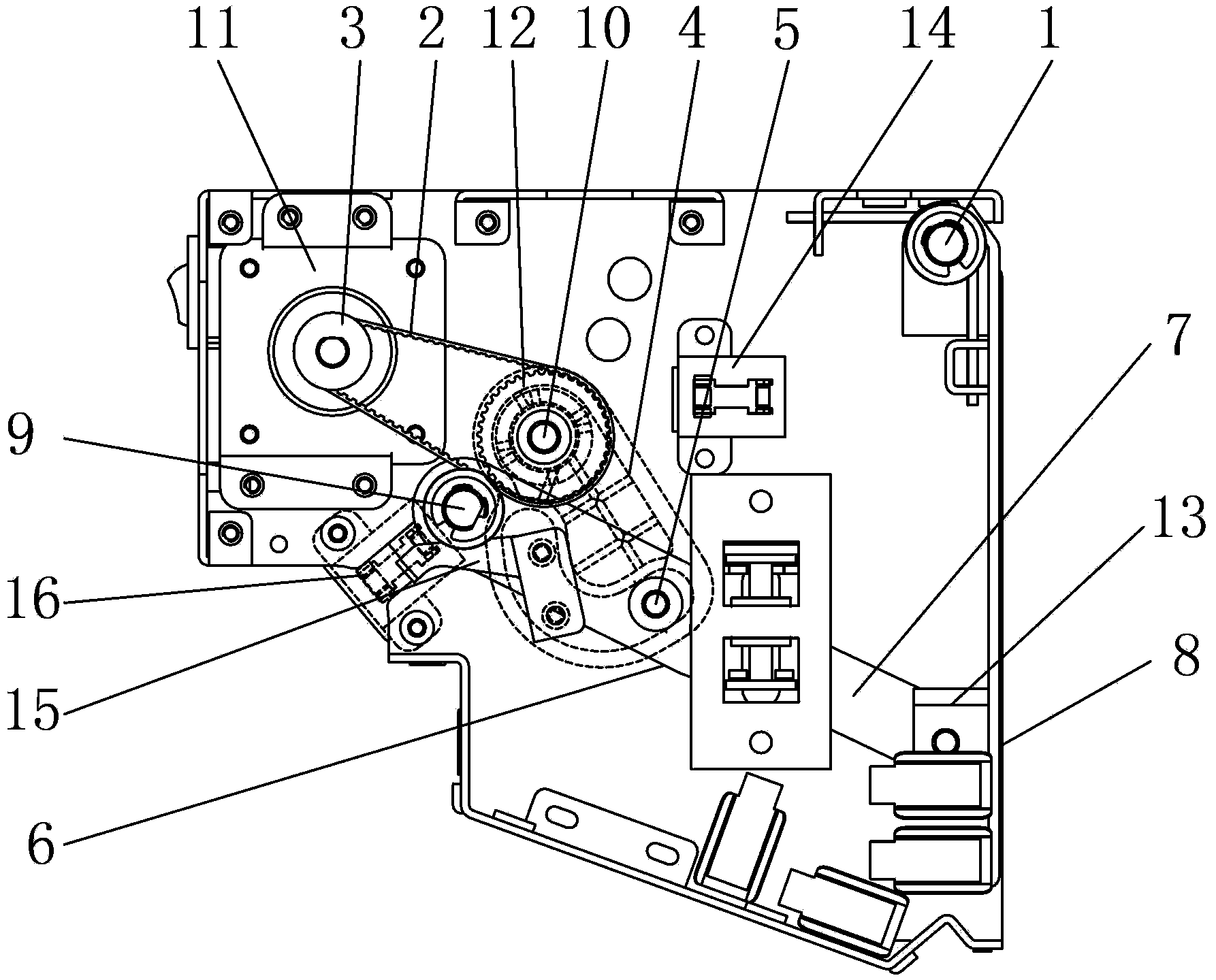
Figure 3
Abstract
Description
technical field
[0001] The invention belongs to the field of mechanical transmission, and in particular relates to a double self-locking transmission mechanism combined with a connecting rod and a cam. Background technique
[0002] Due to its simple and compact structure and fast transmission, the linkage mechanism is frequently used in financial equipment.
[0003] For example, the gate used by the cash outlet of the bank's automatic teller machine uses a motor to drive the crank linkage mechanism. The crank linkage mechanism is connected to the gate plate to realize the opening and closing of the gate, and the movement dead point of the linkage mechanism is used to realize The self-locking of the gate when it is closed prevents the cash withdrawal port from opening by itself under the action of external force.
[0004] However, in actual operation, if a power source such as a motor or a rotating motor is used to directly drive the active link of the linkage mechanism, the...
Examples
Embodiment
[0022] see in conjunction figure 1 , figure 2 and image 3 , the present embodiment takes the banknote outlet gate module of the bank automatic teller machine as an example, a rotating shaft 9 is arranged in the module body, and the two ends of the rotating shaft 9 are arranged on the opposite side plates through bearings, and the active link mechanism One end of the connecting rod 6 is fixed on the rotating shaft 9 and rotates with the rotating shaft 6, the other end of the active connecting rod 6 is hinged with one end of the driven connecting rod 7 of the linkage mechanism, and the other end of the driven connecting rod 7 and the gate plate 8 pass through the connecting block 13 Hinged, the connecting rod mechanism drives the gate plate 8 to rotate around the gate rotating shaft 1 to realize the closing of the opening box of the gate; there are two connecting rod mechanisms, which are respectively arranged at the two ends of the rotating shaft 9 . A cam 4 is provided in ...