Flying automobile wing contraction-release system

A flying car and wing technology, which is applied in the field of flying car wing retraction system, can solve the problems of large overall weight, high cost, difficulty of application, etc.

Inactive Publication Date: 2018-02-13
BEIHANG UNIV
View PDF5 Cites 0 Cited by
  • Summary
  • Abstract
  • Description
  • Claims
  • Application Information

AI Technical Summary

Problems solved by technology

[0003] At present, the most commonly used folding unfolding and folding scheme adopts the wing unfolding and folding scheme of a military carrier-based aircraft, which uses a hydraulic system and a connecting rod system, but it has the following problems: the overall weight is large and the system is complicated It is cumbersome and costly, so it is suitable for military use, and it is difficult and easy to apply to civilian flying cars

Method used


Image

  • Flying automobile wing contraction-release system
  • Flying automobile wing contraction-release system
  • Flying automobile wing contraction-release system

Examples


Embodiment Construction

[0032] The purpose of the present invention is to provide a wing retractable system for a flying car. The provided wing retractable system is safe and reliable, has a simple structure, low manufacturing cost, and is convenient for civil and commercial use.

[0033] In order to enable those skilled in the art to better understand the technical solutions of the present invention, the present invention will be further described in detail below in conjunction with the accompanying drawings and specific embodiments.

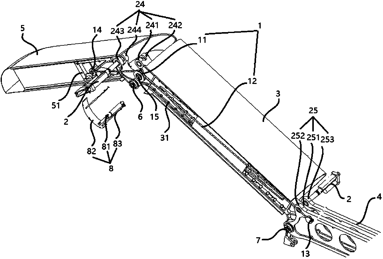
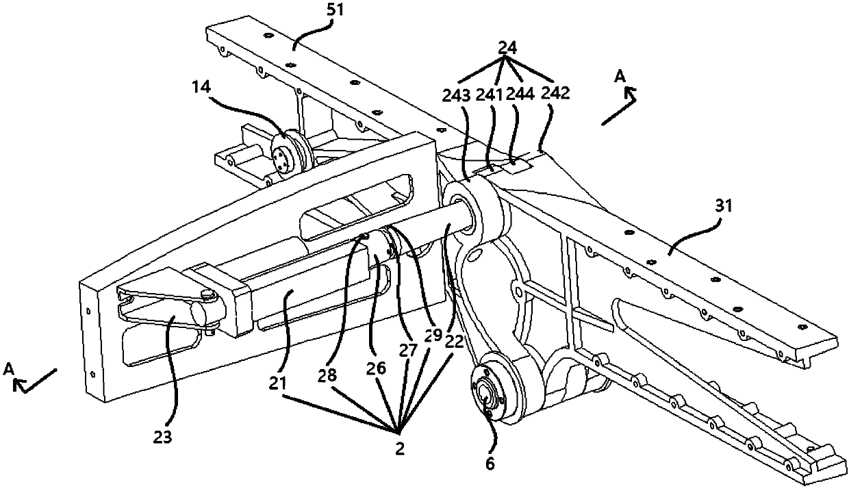
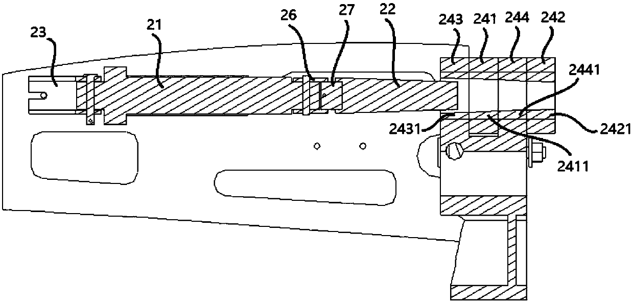
[0034] Such as Figure 1-4 as shown, figure 1 It is a structural schematic diagram of a specific embodiment of the flying car wing retractable system provided by the present invention, figure 2 for figure 1 A schematic diagram of the structure of a retractable locking mechanism, image 3 for figure 2 A cross-sectional view of the A-A direction, Figure 4 for figure 1 Schematic diagram of the structure of the anti-interference mechanism.

[0035] In this specifi...


PUM


Abstract

The invention discloses a flying automobile wing contraction-release system, comprising a contraction-release guide mechanism, two contraction-release locking mechanisms and two skin anti-interferencemechanisms; the contraction-release guide mechanism is used for contracting, releasing and rotating wings; the two contraction-release locking mechanisms are used for ensuring safety and reliabilityfor the contraction and release of the wings; the two skin anti-interference mechanisms are used for ensuring completeness of pneumatic contours of the wings. The flying automobile wing contraction-release system is good in safety and reliability, simple in structure, low in manufacture cost and easy to use for civil and commercial purposes.

Description

technical field [0001] The invention relates to the field of flying cars, and can also be applied to aircrafts such as airplanes with wings, and in particular relates to a flying car wing retractable system. Background technique [0002] Flying cars take up a lot of space when driving and parking on the ground, which is inconvenient. In addition, for flying cars with wings, they need to be folded and stowed when driving on the ground to meet the requirements of national road regulations. The wings are then extended to meet the aerodynamic demands of flight. Therefore, setting up a safe and reliable system capable of unfolding and folding wings for the above-mentioned aircraft has become a technical problem urgently to be solved in this technical field. [0003] At present, the most commonly used folding unfolding and folding scheme adopts the wing unfolding and folding scheme of a military carrier-based aircraft, which uses a hydraulic system and a connecting rod system, bu...

Claims


Application Information

Patent Timeline
Patent Type & Authority Applications(China)
IPC IPC(8): B60F5/02B64C3/56
CPCB60F5/02B64C3/56
Inventor 林海英吴帅李泽宇
Owner BEIHANG UNIV
Why Eureka
Try Eureka