
Method and apparatus for deliberate fluid removal by capillary imbibition

a technology of deliberate fluid removal and imbibition, which is applied in the direction of folding cabinets, borehole/well accessories, cabinets, etc., can solve the problems of ineffective methods, and achieve the effects of enhancing production capacity, and increasing the effective fracture length

Inactive Publication Date: 2001-09-04
SCHLUMBERGER TECH CORP
View PDF11 Cites 188 Cited by
  • Summary
  • Abstract
  • Description
  • Claims
  • Application Information

AI Technical Summary

Benefits of technology

One advantage of the present Invention is that it results in increased effective fracture length, which in turn means that the rate of production and the production capacity will be enhanced. The rate of production is increased due to the additional flowpaths available to the hydrocarbon; and the overall production capacity is increased due to the enlarged drainage area (the region within the hydrocarbon-bearing formation from which the hydrocarbon is effectively extractable).
is that it results in increased effective fracture length, which in turn means that the rate of production and the production capacity will be enhanced. The rate of production is increased due to the additional flowpaths available to the hydrocarbon; and the overall production capacity is increased due to the enlarged drainage area (the region within the hydrocarbon-bearing formation from which the hydrocarbon is effectively extractable).
A second advantage of the present Invention is that since the effective fracture length is increased, the drainage area concomitantly increases, which in turn means that less wells need to be drilled in order to recover a given amount of hydrocarbon from the formation.
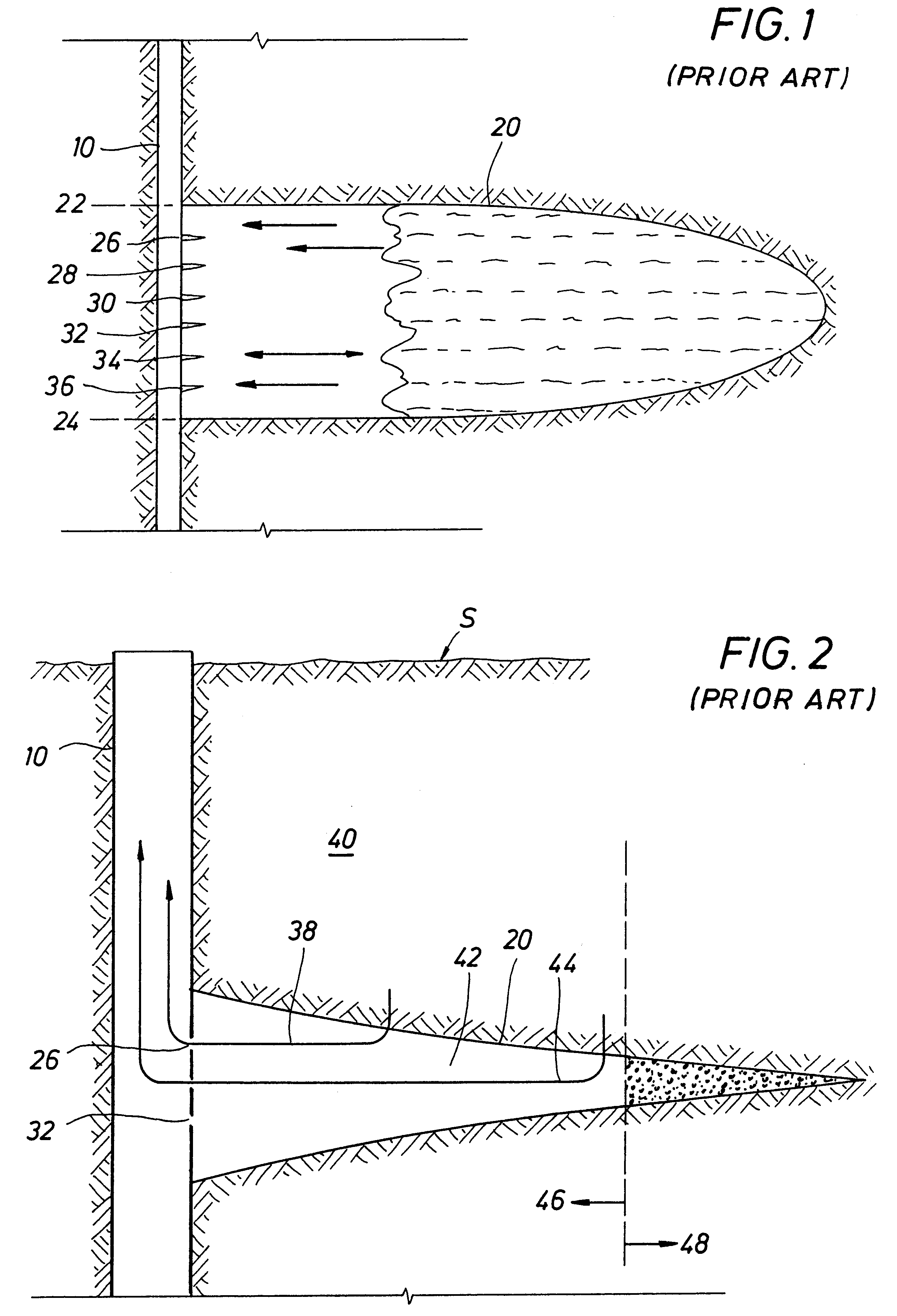
FIG. 1 depicts a stylized cross-sectional view of a typical fracture zone in a subsurface formation.
FIG. 2 depicts a cross-sectional view of a stylized fracture modified to show certain essential features of a typical fracturing operation.
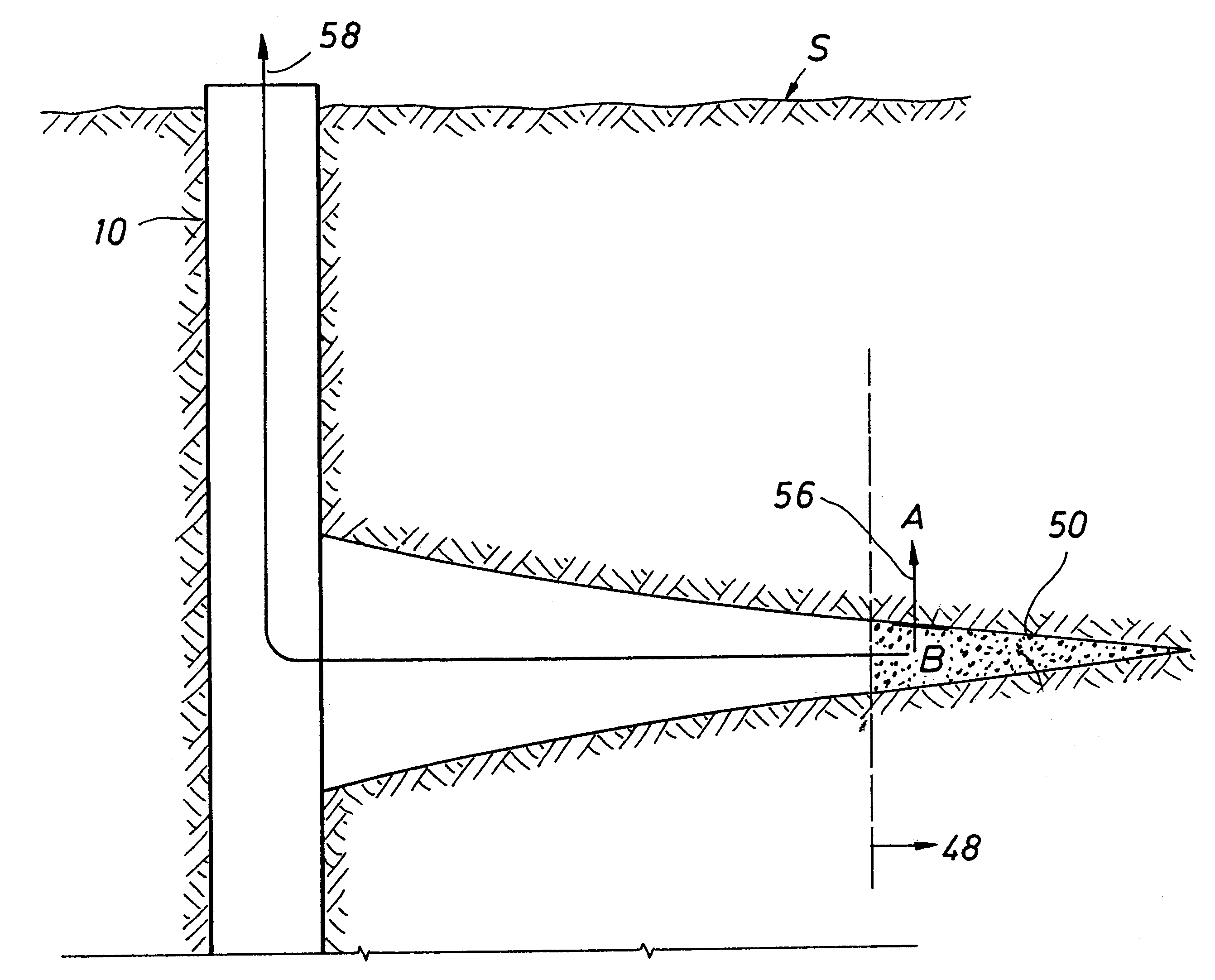
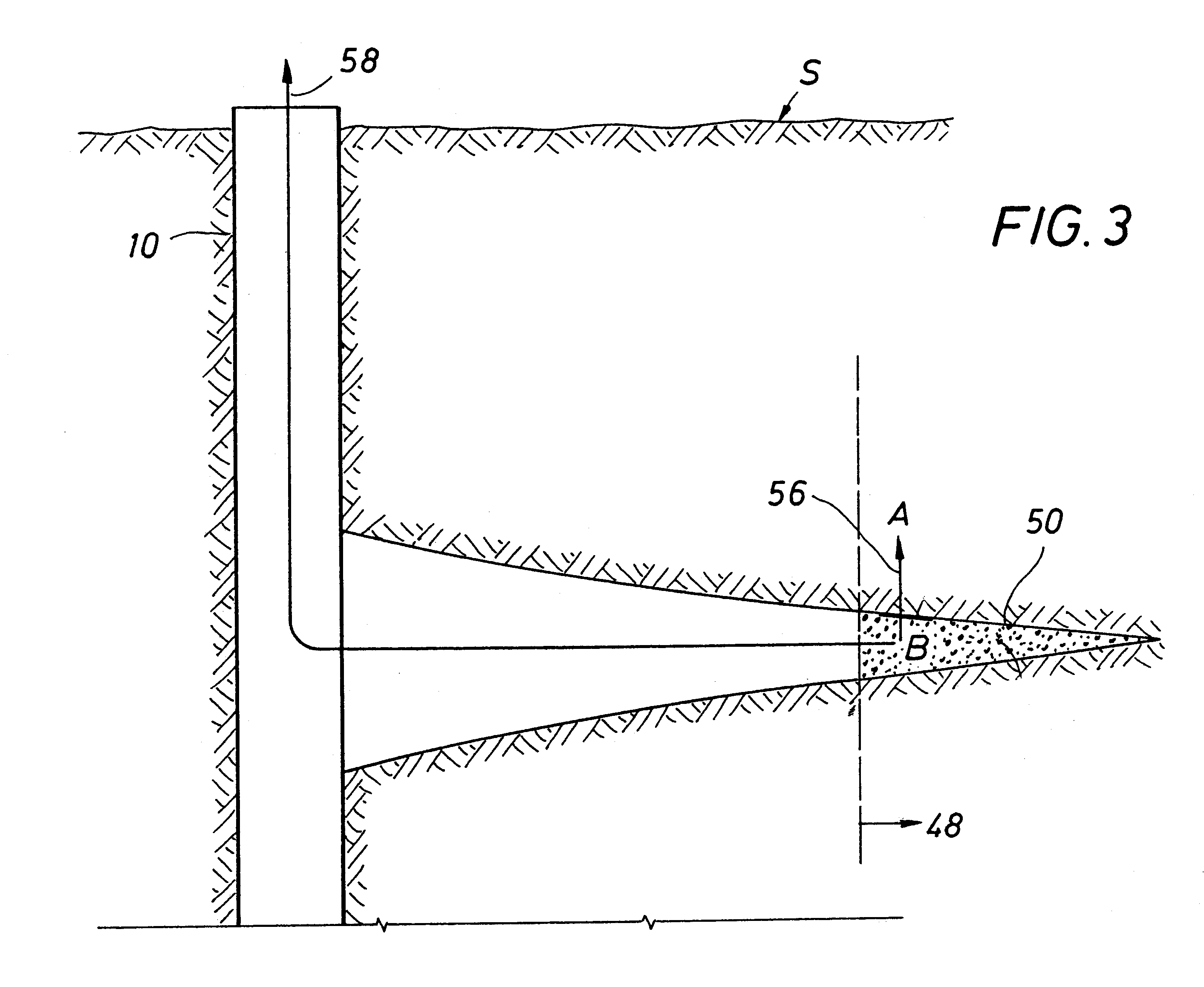
FIG. 3 depicts a cross-sectional view of a stylized fracture modified to show certain essential features of the present Invention.

Problems solved by technology

The problem is that, quite ironically, the fluid used to fracture the formation remains in the fracture and acts as a barrier to putative hydrocarbon migrating into the fracture towards the wellbore.
Generally, speaking, this method has not proven effective--as evidenced at least in part by the fact that the effective fracture length (fluid-free portion of the fracture) is about half of the actual fracture length is, in probably most cases.

Method used


Image

  • Method and apparatus for deliberate fluid removal by capillary imbibition
  • Method and apparatus for deliberate fluid removal by capillary imbibition
  • Method and apparatus for deliberate fluid removal by capillary imbibition

Examples


example 2

Numerical Simulation of Fracture Fluid Clean-up Based on the Empirically Based Flow Parameter

Having obtained this volume flux parameter, we now perform a numerical simulation of fracture clean-up (the movement of spent fracturing fluid out of the fracture and into the formation), based on the laboratory-derived parameter.

To ensure that the results from the computer simulation mimic as closely as possible, real-world conditions, the parameter used to describe flow due to capillary imbibition (J.sub.v, the volume flux due to capillary pressure-induced flow)--the key parameter in the model--was obtained by laboratory experiment, according to Example 1. Put more simply, the study presented in this Example purports to answer the following question: having determined an experimentally based value for the capillary pressure flux, is this flux significant enough to actually move appreciable volumes of fluid from a subsurface fracture tip? Or: can the present Invention be employed to actuall...

example 3

Preferred Fracture Treatment Design

In Example 1, we obtained a laboratory-based flow parameter for capillary imbibition. In Example 2, we used that parameter in a numerical simulator of fluid movement in a fracture to model fracturing fluid clean-up. These examples demonstrate that fracturing treatments could be designed in accordance with the present Invention. Those treatment designs are presented in this Example.

In each example, we assume that the formation is a water-wet formation, as in fact most are. A typical hydraulic fracturing treatment can be conveniently divided into three phases: (1) the pad stage; (2) the proppant slurry stage; and (3) a flush. In a typical fracturing treatment, a pad fluid is first pumped--the purpose is to initiate and propagate (extend) the fracture. A second purpose (not always desired or achieved) is to seal the fracture face to prevent fluid loss as additional fluid is pumped into the fracture during later stages. Generally, though not always, th...


PUM

PropertyMeasurementUnit
lengthaaaaaaaaaa
lengthaaaaaaaaaa
fracture heightaaaaaaaaaa

Abstract

The present Invention relates to hydrocarbon well stimulation, and more particularly to methods and compositions to remove (or more generally to transfer) fluid introduced into the subsurface. For instance, preferred methods involve creating then exploiting a capillary pressure gradient at the fracture face to induce fluid flow from the fracture into the formation thereby increasing effective fracture length, and then improving fracture conductivity.

Description

1. Technical Field of the InventionThe present Invention relates to hydrocarbon well stimulation, and more particularly to methods and compositions to remove (and more generally to transfer) fluid deliberately introduced into the subsurface. For instance, the methods and compositions of the present invention involve creating then exploiting a capillary pressure gradient at the fracture face to systematically induce fluid flow from the fracture into the formation (or from the formation into the fracture), thereby increasing effective fracture length, hence, improving conductivity.This Application is one member of a family of patent applications by Hinkel and England, the Inventors of the present Invention, and assigned to Schlumberger Technology Corporation. The common feature of these Applications is that they are all directed to transferring fluids in the subsurface by non-hydraulic means. The other Applications in this family are, Enhancing Fluid Removal From Subsurface Fractures ...

Claims


Application Information

Patent Timeline
Patent Type & Authority Patents(United States)
IPC IPC(8): C09K8/64C09K8/68C09K8/60E21B43/26E21B43/25
CPCC09K8/64E21B43/26C09K8/685Y10S507/921E21B43/2605
Inventor HINKEL, JERALD J.ENGLAND, KEVIN W.
Owner SCHLUMBERGER TECH CORP
Learn More