Fixation devices for variation in engagement of tissue

a tissue and fixation device technology, applied in the field of medical methods, devices and systems, can solve the problems of more difficult to grasp symmetrically in the same grasp as the other leaflets, and achieve the effects of increasing the length of the distal element, and increasing the size of the engagement surfa

Inactive Publication Date: 2010-10-12
EVALVE
View PDF571 Cites 190 Cited by
  • Summary
  • Abstract
  • Description
  • Claims
  • Application Information

AI Technical Summary

Benefits of technology

[0020]In some embodiments, the devices, systems and methods of the invention are adapted for fixation of tissue at a treatment site. Exemplary tissue fixation applications include cardiac valve repair, septal defect repair, vascular ligation and clamping, laceration repair and wound closure, but the invention may find use in a wide variety of tissue approximation and repair procedures. In a particularly preferred embodiment, the devices, systems and methods of the invention are adapted for repair of cardiac valves, and particularly the mitral valve, as a therapy for regurgitation. The invention enables two or more valve leaflets to be coapted using an “edge-to-edge” or “bow-tie” technique to reduce regurgitation, yet does not require open surgery through the chest and heart wall as in conventional approaches. In addition, the position of the leaflets may vary in diseased mitral valves depending upon the type and degree of disease, such as calcification, prolapse or flail. These types of diseases can result in one leaflet being more mobile than the other (e.g. more difficult to capture), and therefore more difficult to grasp symmetrically in the same grasp with the other leaflet. The features of the present invention allow the fixation devices to be adapted to meet the challenges of unpredictable target tissue geometry, as well as providing a more robust grasp on the tissue once it is captured.
[0026]In a first aspect of the present invention, fixation devices are provided that include at least two distal elements and an actuatable feature attached to at least one of the at least two distal elements. Actuation of the feature varies a dimension of at least one of the at least two distal elements which varies the size of its engagement surface. For example, in some embodiments, the actuatable feature is configured so that actuation varies the width of the distal element. In some of these embodiments, the actuatable feature comprises at least one loop which is extendable laterally outwardly in a direction perpendicular to the longitudinal axis. Thus, extension of the at least one loop increases the size of the engagement surface of the distal element, specifically the width. In others of these embodiments, the actuatable feature comprises at least one flap which is extendable laterally outwardly in a direction perpendicular to the longitudinal axis. And in still others, the actuatable feature comprises at least one pontoon which is expandable laterally outwardly in a direction perpendicular to the longitudinal axis. The pontoon may be expanded by inflation or any suitable means.
[0027]In some embodiments, the actuatable feature is configured so that actuation varies the length of the distal element. In some of these embodiments, the actuatable feature comprises at least one loop which is extendable laterally outwardly from its free end along its longitudinal axis. Thus, extension of the at least one loop increases the size of the engagement surface of the distal element, specifically the length. In others of these embodiments, each of the distal elements comprises an elongate arm and the actuatable feature comprises an extension arm coupled with the elongate arm. The extension arm is extendable from the elongate arm to increase the length of the distal element. For example, in some instances the extension arm is coupled with the elongate arm by a cam such that rotation of the cam advances the extension arm along the longitudinal axis. Extension or retraction of the extension arm may be actuated by movement of the fixation device. For example, when each distal element is moveable from a closed position (wherein the engagement surfaces of the at least two distal elements are closer together) to an open position (wherein the engagement surfaces of the at least two distal elements are further apart), movement between the closed and open position may advance the extension arm of each distal element along its longitudinal axis.
[0029]In a third aspect of the present invention, accessories are provided which may be used with fixation devices of the present invention. Such accessories may provide benefits which are similar to increasing the width and / or length of the distal elements. Thus, such accessories may be used with fixation devices of fixed dimension or with fixation devices having distal elements of varying dimensions.

Problems solved by technology

These types of diseases can result in one leaflet being more mobile than the other (e.g. more difficult to capture), and therefore more difficult to grasp symmetrically in the same grasp with the other leaflet.

Method used


Image

  • Fixation devices for variation in engagement of tissue
  • Fixation devices for variation in engagement of tissue
  • Fixation devices for variation in engagement of tissue

Examples


Embodiment Construction

I. Fixation Device Overview

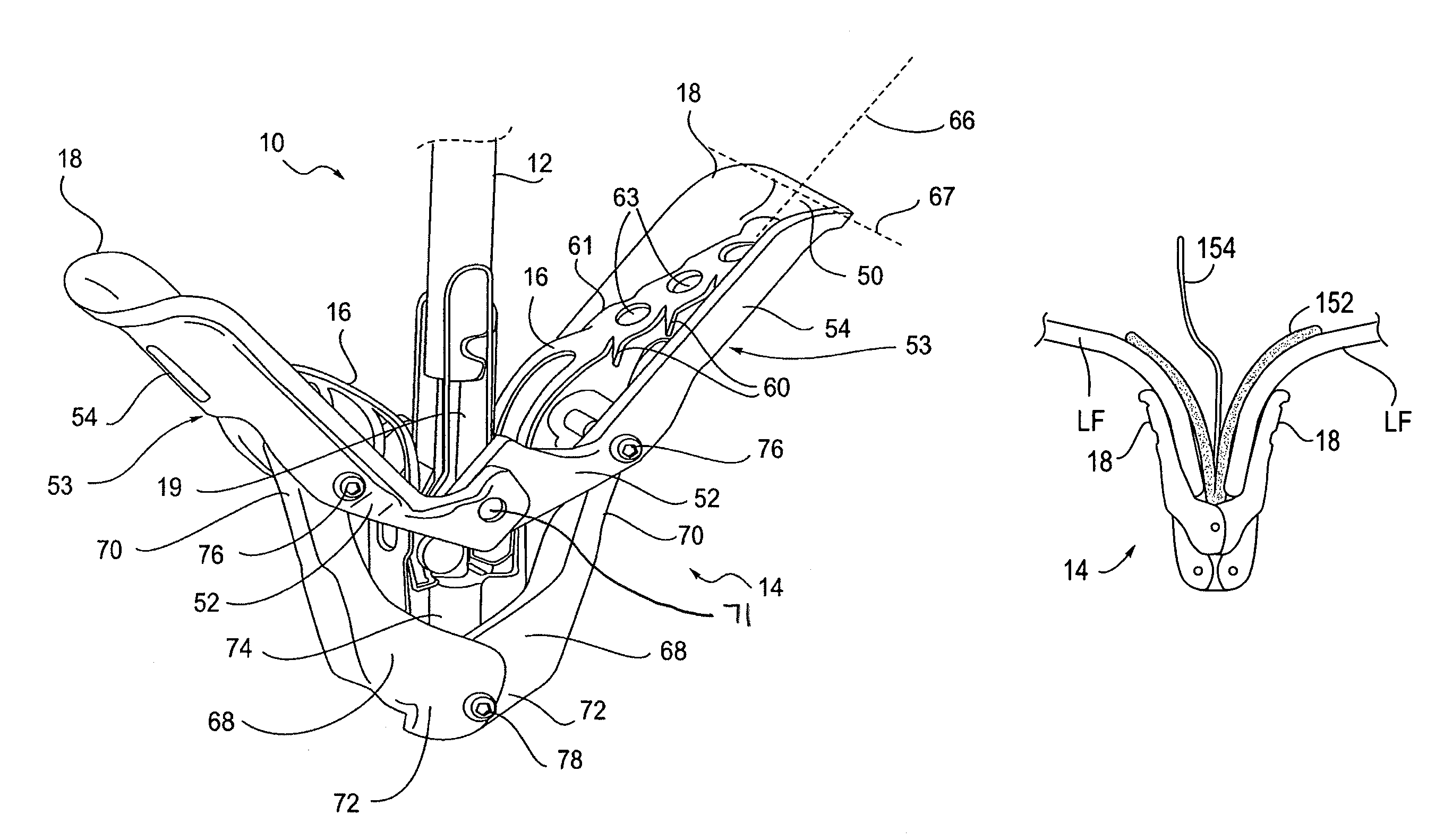
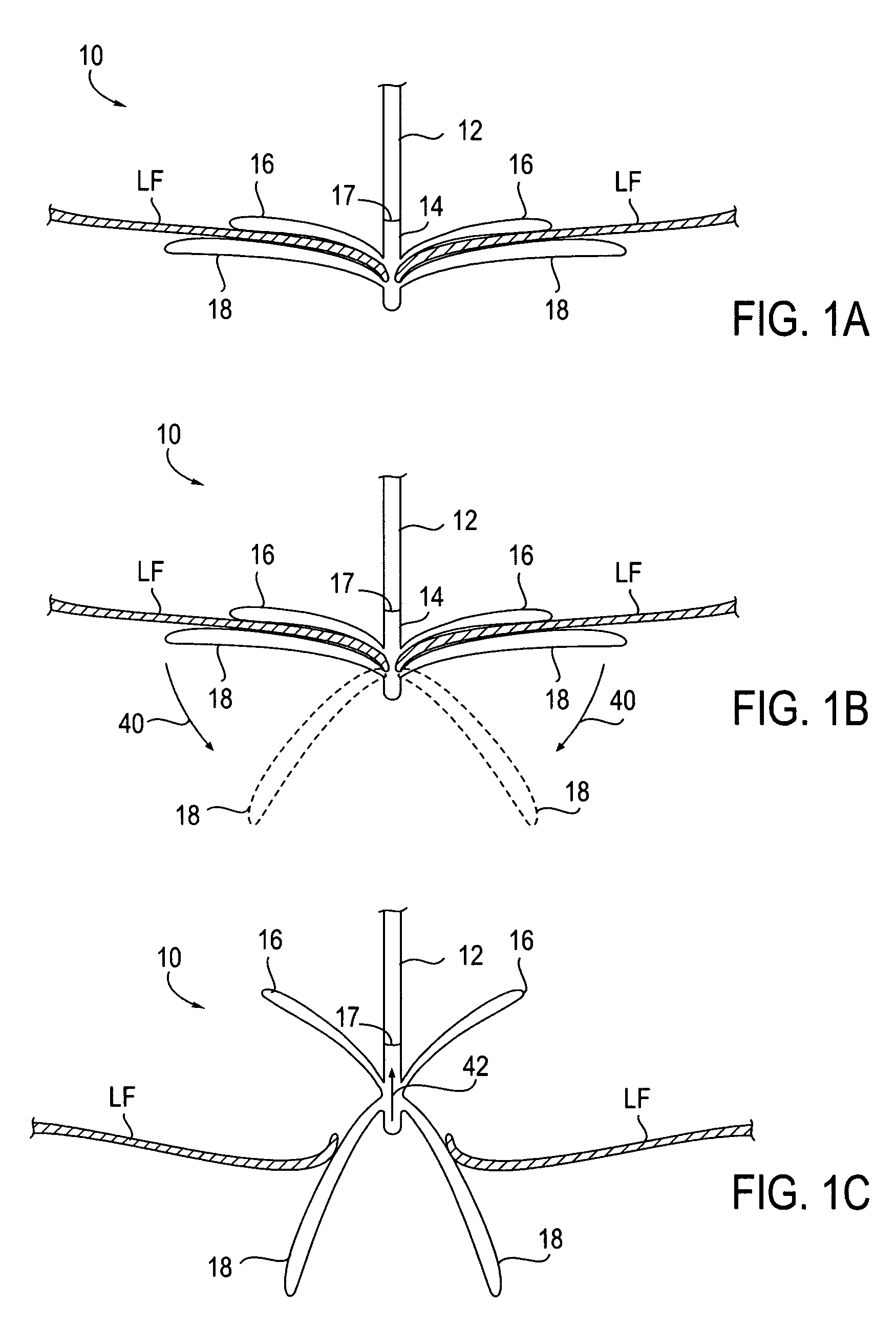
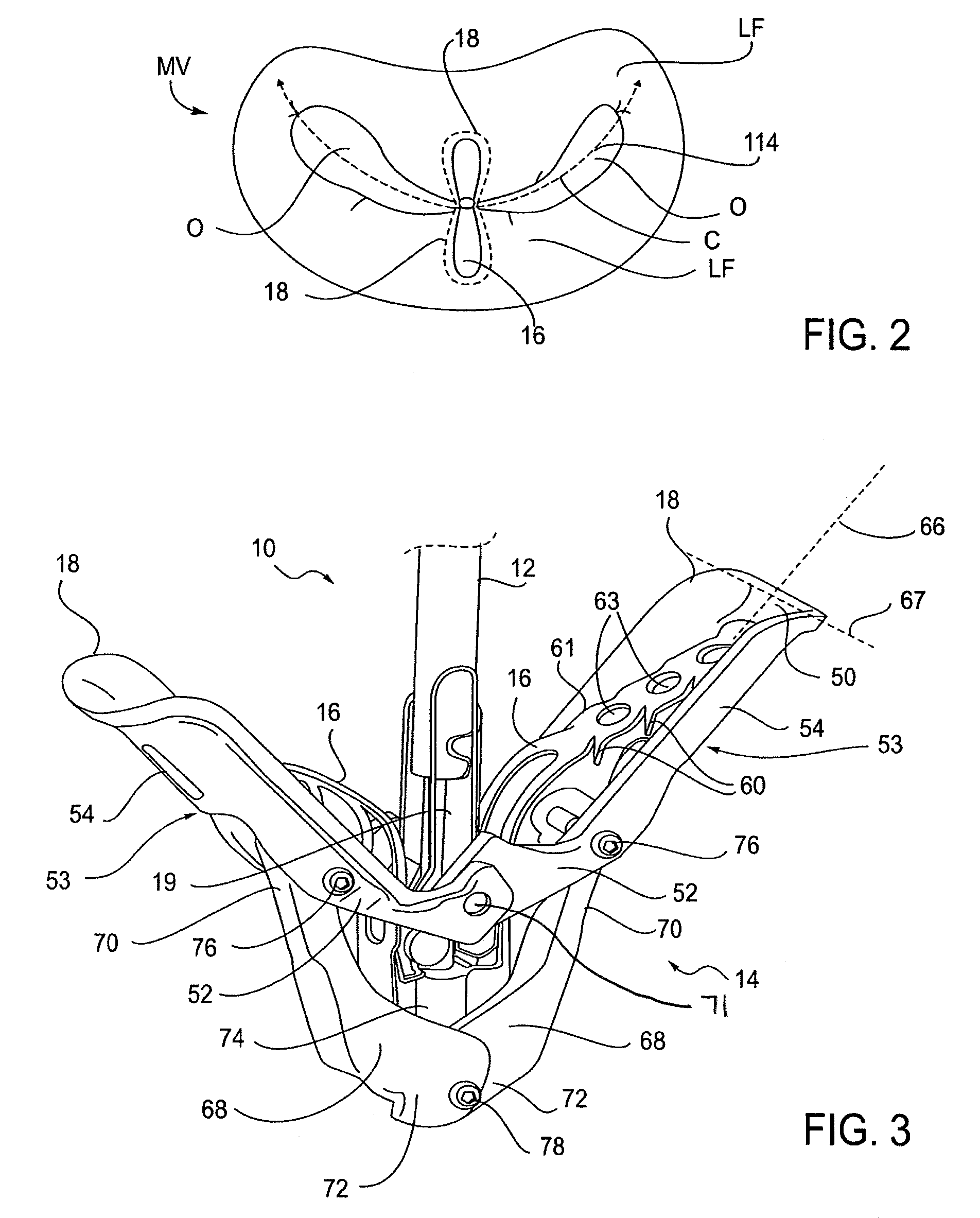
[0049]The present invention provides methods and devices for grasping, approximating and fixating tissues such as valve leaflets to treat cardiac valve regurgitation, particularly mitral valve regurgitation.

[0050]Grasping may be atraumatic which can provide a number of benefits. By atraumatic, it is meant that the devices and methods of the invention may be applied to the valve leaflets and then removed without causing any significant clinical impairment of leaflet structure or function. The leaflets and valve continue to function substantially the same as before the invention was applied. Thus, some minor penetration or denting of the leaflets may occur using the invention while still meeting the definition of “atraumatic”. This enables the devices of the invention to be applied to a diseased valve and, if desired, removed or repositioned without having negatively affected valve function. In addition, it will be understood that in some cases it may be nec...


PUM


Abstract

Devices, systems and methods are provided for tissue approximation and repair at treatment sites, particularly in those procedures requiring minimally-invasive or endovascular access to remote tissue locations. Fixation devices are provided to fix tissue in approximation with the use of distal elements. In some embodiments, the fixation devices have at least two distal elements and an actuatable feature wherein actuation of the feature varies a dimension of the at least two distal elements. In other embodiments, the fixation devices have at least two pairs of distal elements wherein the pairs of distal elements are moveable to engage tissue between opposed pairs of distal elements. Systems are also provided having fixation devices and accessories.

Description

CROSS-REFERENCES TO RELATED APPLICATIONS[0001]The present application is a continuation-in-part of copending U.S. application Ser. No. 10 / 803,444 filed Mar. 17. 2004 which is a continuation of U.S. application Ser. No. 09 / 894,463 filed Jun. 27, 2001, (now U.S. Pat. No. 6,752,813 issued Jun. 22, 2004), which is a continuation-in-part of U.S. patent application Ser. No. 09 / 544,930 filed Apr. 7, 2000 (now U.S. Pat. No. 6,629,534) and which claims priority from U.S. Provisional Application No. 60 / 128,690, filed Apr. 9, 1999.STATEMENT AS TO RIGHTS TO INVENTIONS MADE UNDER FEDERALLY SPONSORED RESEARCH OR DEVELOPMENT[0002]NOT APPLICABLEREFERENCE TO A “SEQUENCE LISTING,” A TABLE, OR A COMPUTER PROGRAM LISTING APPENDIX SUBMITTED ON A COMPACT DISK[0003]NOT APPLICABLEBACKGROUND OF THE INVENTION[0004]1. Field of the Invention[0005]The present invention relates generally to medical methods, devices, and systems. In particular, the present invention relates to methods, devices, and systems for th...

Claims


Application Information

Patent Timeline
Patent Type & Authority Patents(United States)
IPC IPC(8): A61B17/08
CPCA61B17/122A61B17/1285A61B2017/00243A61B2017/00783A61B2017/081A61F2/246A61F2220/0091
Inventor GOLDFARB, ERIC A.RASCHDORF, ALFRED H.SARABIA, JAIME E.FAN, SYLVIA WEN-CHINDELL, KENT D.KOMTEBEDDE, JANPOWELL, FEROLYN
Owner EVALVE
Why Eureka
Try Eureka