Stent delivery system

Inactive Publication Date: 2005-02-03
MEDTRONIC VASCULAR INC
View PDF23 Cites 51 Cited by
  • Summary
  • Abstract
  • Description
  • Claims
  • Application Information

AI Technical Summary

Benefits of technology

[0010] The system may include a valve relief that is selectively coupled to the catheter. By coupling the valve relief to t

Problems solved by technology

The large diameter of the delivery catheter may in turn increase the risk of complications at the patient access site.
The increased profile also detracts from the ability of the device to navigate through tortuous vessels or passageways.
The increased cross-sectional profile of the delivery system may make it impossible to deliver a self expanding stent to the treatment area and may decrease the ability to deliver sufficient contrast material through the guide catheter for enabling precise positioning.
I

Method used


Image

  • Stent delivery system
  • Stent delivery system
  • Stent delivery system

Examples


Embodiment Construction

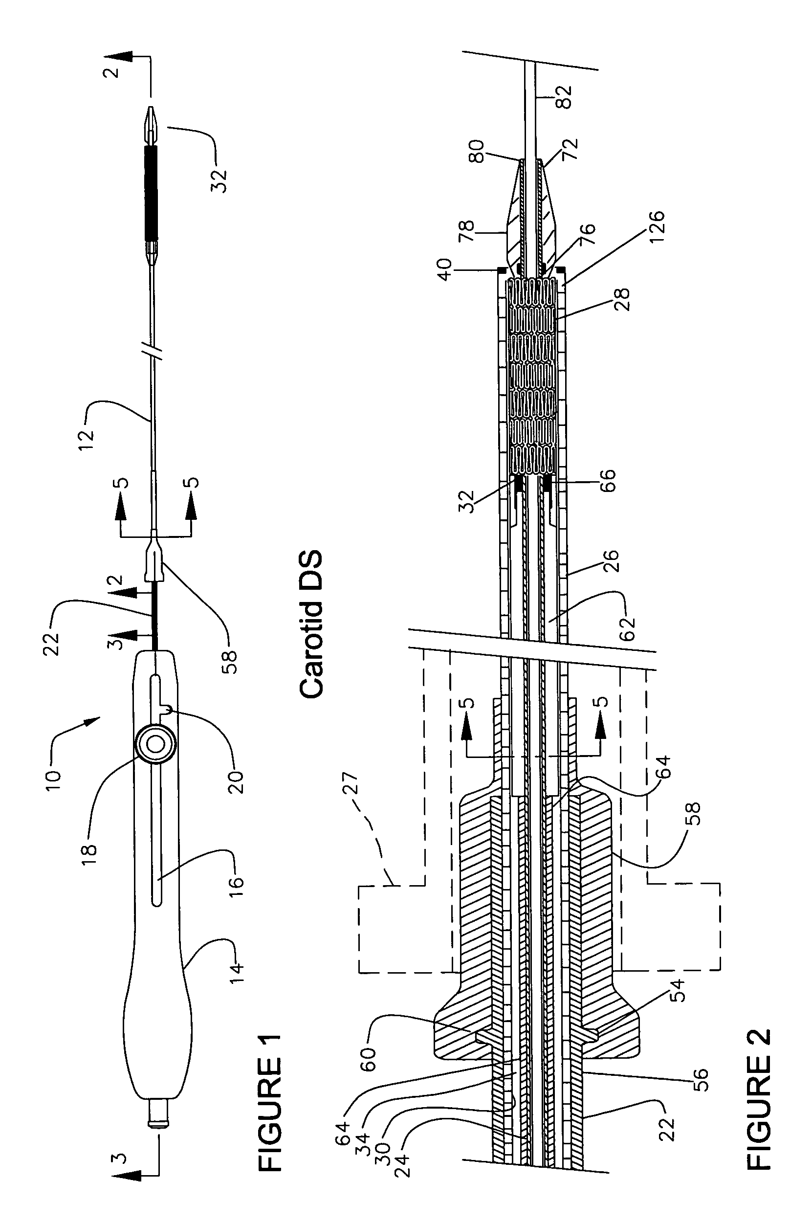
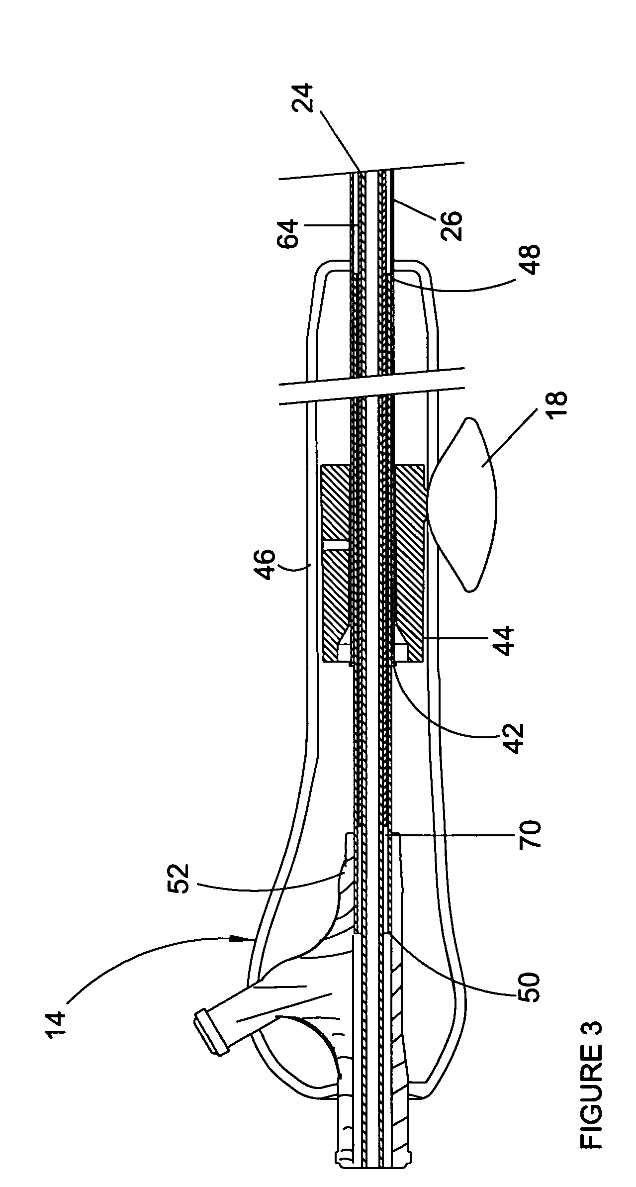
[0029] The present invention is a system for delivering a self expanding stent. Stent delivery system, designated 10 in FIG. 1, consists of an elongated member 12 and a handle 14. Handle 14 includes a longitudinal slot 16 along which knob 18 can reciprocate. A transverse slot 20 is located at the distal end of longitudinal slot 16 and knob 18 can rotate and enter transverse slot 20. A strain relief 22 is located at handle 14 distal end and surrounds the proximal exterior of elongated member 12 to provide a smooth transition between handle 14 and elongated member 12.

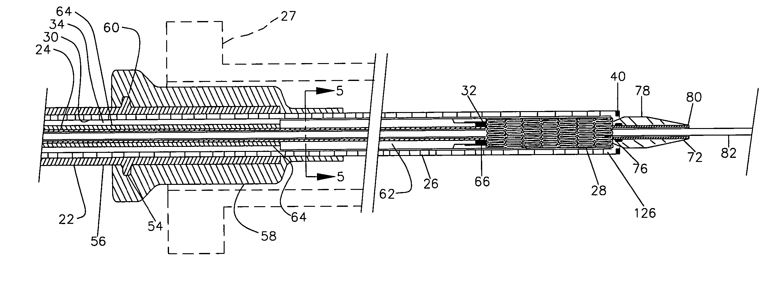
[0030] Turning now to FIGS. 2 and 3, elongated member 12 comprises an inner shaft 24 and an outer shaft 26. The outer shaft 26 is moveable with respect to the inner shaft 24 for releasing stent 28 at the desired treatment site. Outer shaft 26 is preferably a braided composite consisting of a nylon outer jacket, a stainless steel wire braid and a polyether block amide inner layer. Outer shaft 26 inner lumen surface 30 is ...


PUM

PropertyMeasurementUnit
Lengthaaaaaaaaaa
Areaaaaaaaaaaa
Radiopacityaaaaaaaaaa

Abstract

The present invention is a device for delivering a self-expanding stent. The device has an inner shaft and an outer shaft moveable with respect to the inner shaft. The self expanding stent is received on the inner shaft adjacent its distal end. A tapered tip is located on the inner shaft distal end and it forms a smooth transition from the delivery device to the guide wire extending therethrough. A handle allows the practitioner to deploy the stent single handedly. The stent may have its segments in a first radial configuration for deliver of the stent or the stent may have a plurality of segments in a first radial configuration and a plurality of second segments in a second radial position.

Description

RELATED APPLICATIONS [0001] This application is a divisional of and claims priority from U.S. patent application Ser. No. 09 / 691,650 filed Dec. 17, 2000.FIELD OF THE INVENTION [0002] The present invention relates generally to methods and devices for delivering and deploying a medical endoprosthesis, and more particularly to a delivery system for a self-expanding endoprosthesis. BACKGROUND OF THE INVENTION [0003] Medical endoprostheses, commonly referred to as stents, are known in the prior art for maintaining the patency of a diseased or weakened vessel or other passageway. Stents have been implanted in various body passageways such as blood vessels, the urinary tract, the biliary tract, and other body lumens. These devices are inserted into the vessel, positioned across the treatment area and then expanded or allowed to self expand to keep the vessel or passageway open. Effectively, the stent overcomes the natural tendency of the weakened area to close. Stents used in the vascular ...

Claims


Application Information

Patent Timeline
IPC IPC(8): A61F2/06A61F2/84
CPCA61F2/95A61F2002/9517A61F2002/9522Y10T29/53917Y10T29/49908Y10T29/49925Y10T29/49872Y10T29/49863A61F2/9517A61F2/9522
Inventor KRIVORUCHKO, MIKEBERTHIAUME, WILLIAMTRAN, DONKRISTOFFERSEN, KRISGRISWOLD, ERIKSWANSON, VANCESINGKEO, SOMBOUNEBILGE, FERTACMILLER, SEAN
Owner MEDTRONIC VASCULAR INC
Why Eureka
Try Eureka