Drive apparatus

a drive device and drive shaft technology, applied in the field of tissue cutting and removal systems, can solve the problems of true back problems, pain from nerve irritation and compression, and the inability to work,

Inactive Publication Date: 2006-04-13
SURGITECH
View PDF27 Cites 71 Cited by
  • Summary
  • Abstract
  • Description
  • Claims
  • Application Information

AI Technical Summary

Benefits of technology

[0013] Embodiments of the invention overcome some or all of the above disadvantages by providing systems and methods for tissue cutting and removal including a shielded reciprocating surgical file and a direct vision apparatus. Some embodiments provide surgical instrumentation that allows a surgeon to navigate into the tiny neuroforamen next to delicate nerves under direct vision, and locate and remove obstructions of tissue that can cause nerve compression and irritation. Advantageously, this offers many patients a minimally invasive surgical option that can result in shorter hospital stays and lower cost.
[0014] Embodiments of the invention can desirably be adapted and tailored to serve at least three surgical fields. These include, but are not limited to, neurosurgery, orthopaedic surgery and plastic surgery. The neurosurgical embodiments enable surgeons to safely enlarge the constricted neuroforamen and provide more space for the nerve roots to pass through the rigid bony vertebral structure, thereby relieving the nerve pinching and compression.
[0017] In some embodiments the housing is concave about at least a portion of its long axis, such as at least a distal portion of its long axis. In some embodiments the housing is convex about at least a portion of its long axis, such as at least a distal portion of its long axis. In some embodiments the first opening is in an opening surface on the housing. In some embodiments the housing is curved along its long axis, to assist in placing the surgical instrument in the body of a patient. In some embodiments the blade is substantially flat.
[0023] In some embodiments at least one bearing comprises the two surfaces. In some embodiments two bearings respectively comprise the two surfaces. In some embodiments the curvilinear body is disposed at an angle to the central axis of the cam. Some embodiments include a pump comprising: a fluid path; two plungers configured to at least partially occlude the fluid path; a cam configured to cause the two plungers to at least partially occlude the fluid path alternatingly; and at least one check valve along the fluid path for reducing backflow of fluid within the fluid path.
[0024] In some embodiments the cam translates in a direction that is substantially perpendicular to a long axis of at least one of the two plungers. In some embodiments the cam translates in a direction that is substantially perpendicular to a long axis of each of the two plungers. In some embodiments the pump comprises: a fluid path; two plungers configured to at least partially occlude the fluid path; a cam configured to cause the two plungers to at least partially occlude the fluid path alternatingly; and at least one check valve along the fluid path for reducing backflow of fluid within the fluid path.
[0026] Some embodiments further comprise a handpiece coupled to the housing. Some embodiments further comprise a video camera. In some embodiments the camera is configured to couple with a fiberoptic that extends to a distal end of the housing. In some embodiments a video camera is located in the handpiece. Some embodiments further comprise a watertight seal in the handpiece. In some embodiments the handpiece is configured to contain the video camera in a chamber such that the watertight seal reduces or prevents ingress of at least one of water and bacteria from outside the handpiece into the chamber containing the video camera in the handpiece.

Problems solved by technology

Many million suffer from truly problematic back pain that either keeps them out of work or debilitates them in some way.
Many vertebral and disc injuries result in pain from nerve irritation and compression.
When an intervertebral disc is damaged, often it is because of a physical overrotation between two vertebrae and normal wear and tear.
When a vertebra is overrotated, small facet joints called the zygapophyseal capsules that are located to the left and right sides of the disc are damaged.
When the body incurs damage to these small joints, unwanted osteophytes and bony overgrowths frequently occur at the edges of these tiny joints.
The unwanted bony overgrowth restricts the neuroforamen and pinches the delicate and sensitive nerve roots.
Pinched nerves that are constrained in between vertebras can cause neck and back pain.
The bony overgrowth and a reduction in the space between vertebras pinch the nerves causing irritation, pain and numbness.
The pinching can potentially result in a loss of use of the limbs controlled by the affected nerve.
Thus, when intervertebral discs are damaged from accident, age and / or general wear and tear the intervertebral nerve roots in the neuroforamen are irritated and pinched and can cause unwanted involuntary muscular contractions.
This becomes a severely painful, self-destructive and self-feeding problem.
This causes added strain on the disc above and below the now rigid bone fusion.
Sometimes the attempted fusion of one vertebra onto another vertebra is unsuccessful and does not provide the intended fusion.
Disadvantageously, the intervertebral fusion is an invasive and relatively complicated procedure.
In addition, and undesirably, the fusion process can result in a long hospital stay for the patient, a long recuperation and rehabilitation period and high costs for both the patient and care providers.

Method used


Image

  • Drive apparatus
  • Drive apparatus
  • Drive apparatus

Examples


Embodiment Construction

[0080] The preferred embodiments of the invention described herein relate generally to systems and methods for tissue cutting and removal and, in particular, to a shielded reciprocating surgical file system for cutting, removing, shaping and sculpturing bone and / or tissue material under direct vision.

[0081] While the description sets forth various embodiment specific details, it will be appreciated that the description is illustrative only and should not be construed in any way as limiting the invention. Furthermore, various applications of the invention, and modifications thereto, which may occur to those who are skilled in the art, are also encompassed by the general concepts described herein.

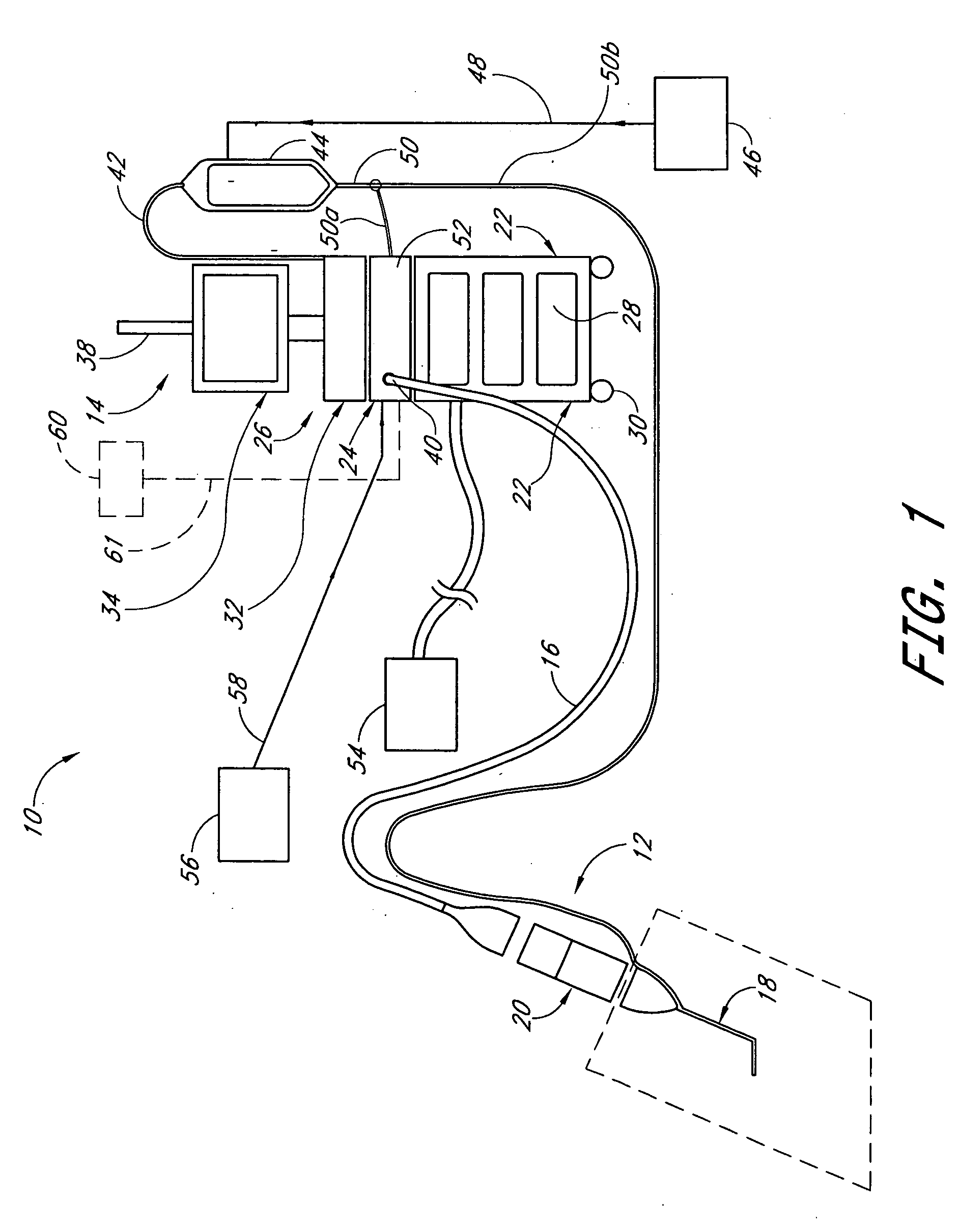
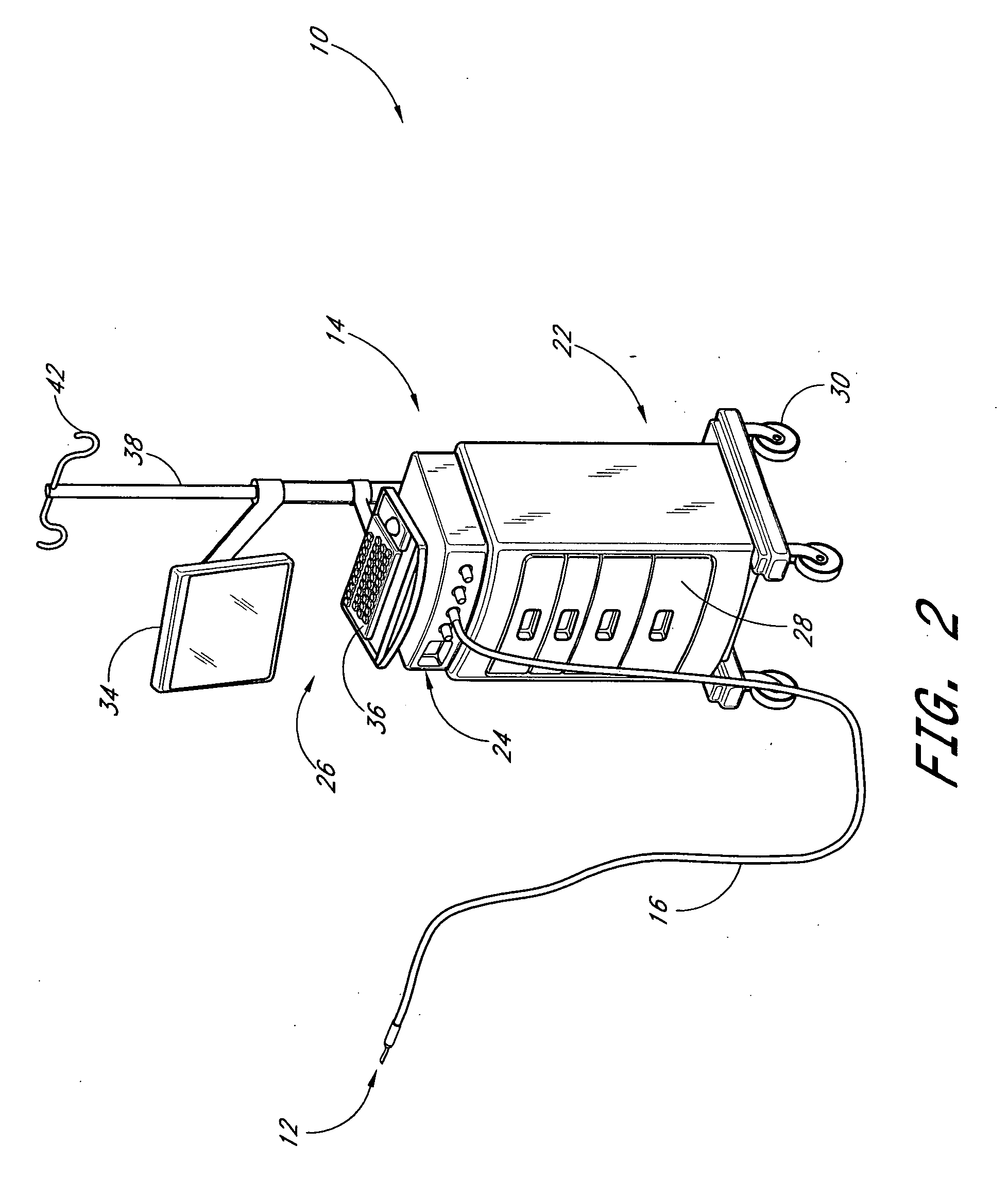
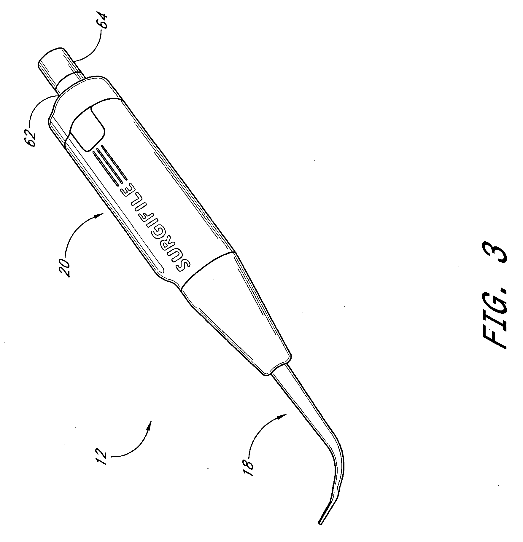
[0082]FIGS. 1 and 2 show a surgical file system 10 generally comprising a motorized reciprocating shielded surgical file instrument, apparatus, assembly or device 12 and a mobile portable control system 14 connected via a flexible umbilical cable 16. The surgical file device 12 generally co...


PUM


Abstract

The invention relates to shielded reciprocating surgical file system for precisely removing bone and / or other tissue material. The system allows a user to maneuver the system and navigate into hard to access sites under a direct vision mechanism included in the system. A transmission mechanism converts rotary motion from a motor into reciprocating motion and provides it to the surgical file for precision bone and / or tissue removal. A pulsatile pump mechanism is operatively coupled with the transmission mechanism and provides irrigating fluid to the surgical site.

Description

RELATED APPLICATIONS [0001] This application is a continuation of U.S. patent application Ser. No. 10 / 675,068 filed Sep. 29, 2003, entitled SHIELDED RECIPROCATING SURGICAL FILE and also claims priority from U.S. Provisional Application No. 60 / 414,690 filed Sep. 27, 2002, entitled SHIELDED RECIPROCATING SURGICAL FILE, the entireties of which are hereby incorporated by reference herein.BACKGROUND OF THE INVENTION [0002] 1. Field of the Invention [0003] The invention relates generally to systems and methods for tissue cutting and removal. More particularly, the invention relates to a shielded reciprocating surgical file system for cutting, removing, grinding, shaping and sculpturing bone and / or tissue material under direct vision. [0004] 2. Description of the Related Art [0005] Adjacent spinal vertebrae are spaced by intervertebral discs that are tough and semi-elastic. The discs act as a flexible spacer between the vertebrae that makeup the backbone. Vertebrae are shaped to provide a ...

Claims


Application Information

Patent Timeline
Patent Type & Authority Applications(United States)
IPC IPC(8): A61B17/32A61BA61B1/00A61B1/07A61B1/313A61B17/16
CPCA61B1/00165A61B1/00167A61B1/07A61B1/3135A61B17/1624A61B17/1659A61B17/1671A61B2017/320028A61B1/015
Inventor HARP, RICHARD J.
Owner SURGITECH
Why Eureka
Try Eureka