
Anchoring elements for intracardiac devices

a technology of anchoring elements and intracardiac devices, which is applied in the field of stabilizing and anchoring elements for improving the stability of intracardiac devices, can solve the problems of increasing the difficulty of properly anchoring a replacement mitral valve in place, affecting and preventing blood leakage, etc., to achieve the effect of preventing paravalvular leakage, preventing leakage of blood, and contributing to the stability of the devi

Inactive Publication Date: 2014-07-17
MVALVE TECH
View PDF1 Cites 176 Cited by
  • Summary
  • Abstract
  • Description
  • Claims
  • Application Information

AI Technical Summary

Benefits of technology

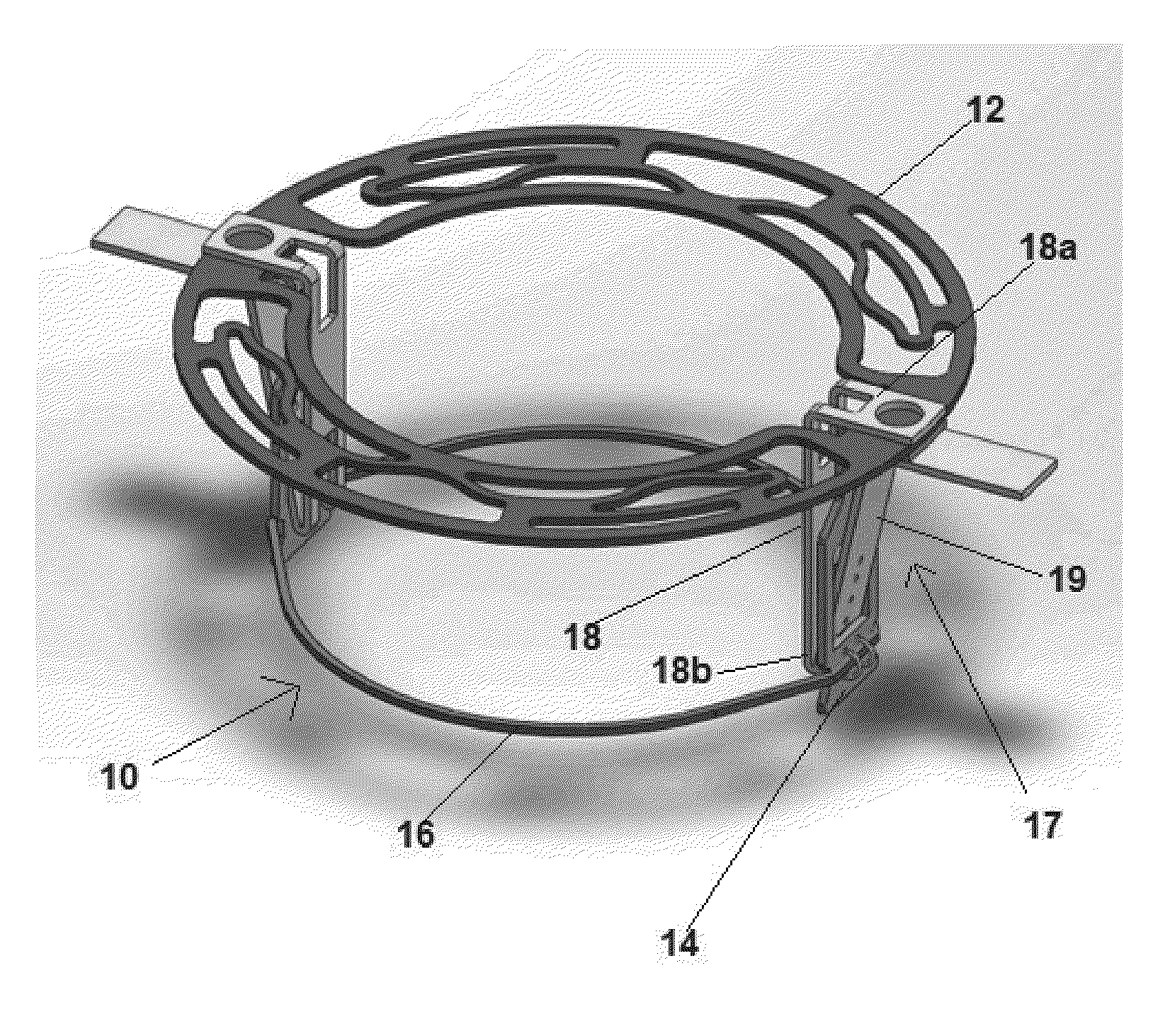
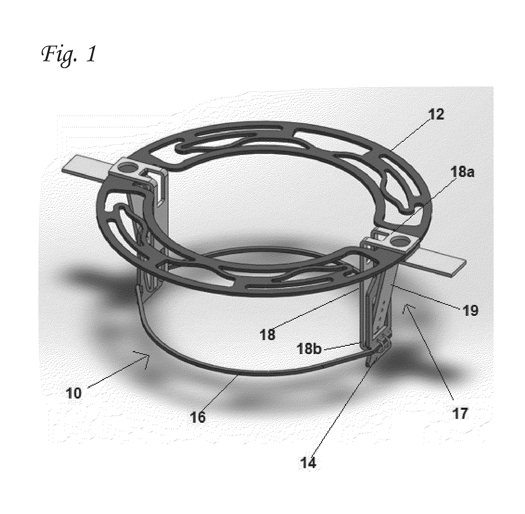
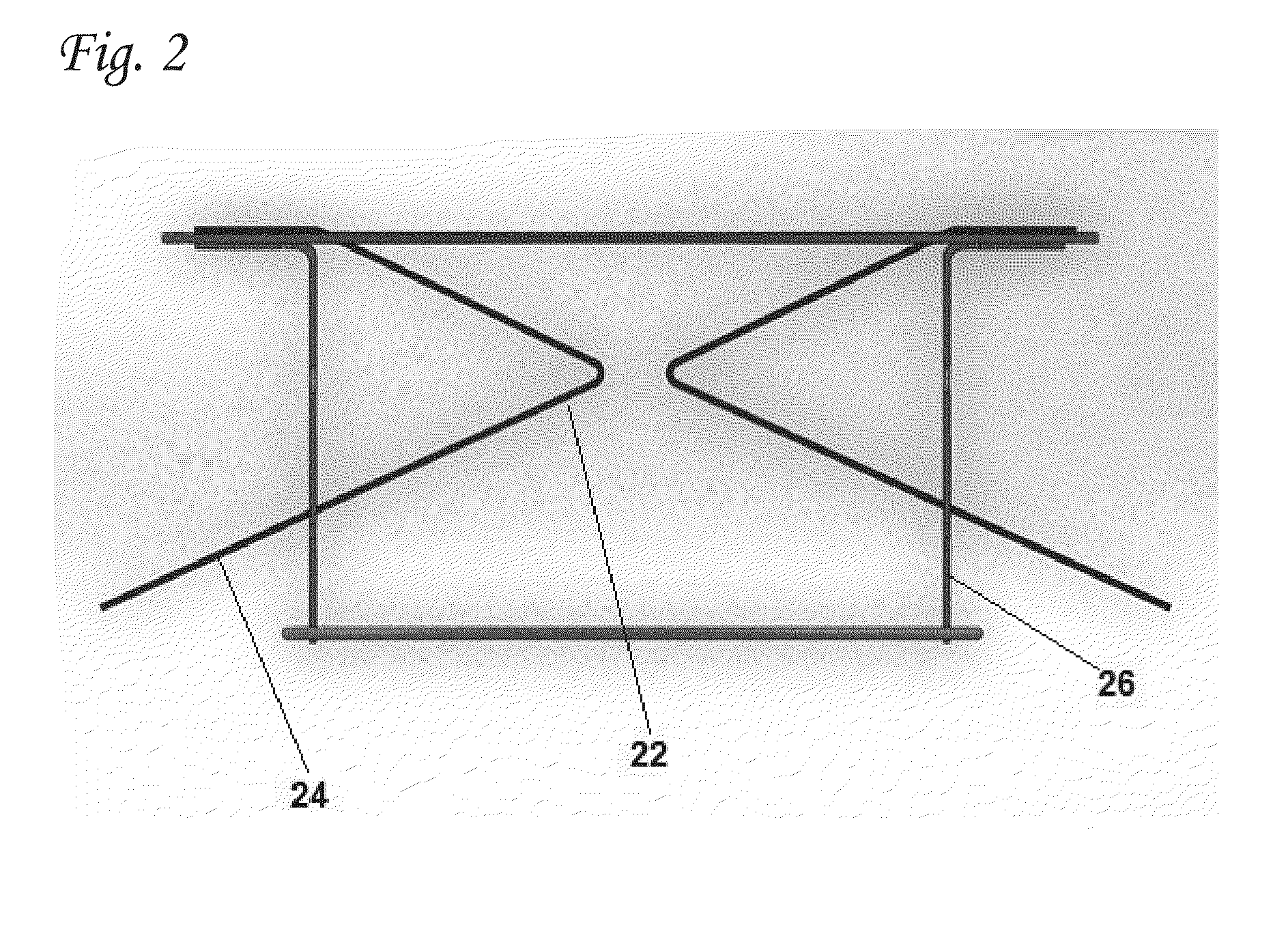
The present invention provides an improved method for stabilizing and anchoring intracardiac devices during heart valve replacement procedures. The invention solves the problem of paravalvular leakage and improves the co-axial positioning of devices. The invention uses a replacement valve that expands during the procedure, which causes the anchoring arms to pivot about their fulcrum and transfer the radial forces to the heart wall. The force-generating step is the expansion of the replacement valve, which results in the high-magnitude forces being applied at the right moment when the native valve leaflets become immobilized. The invention also includes a method for increasing the stabilization of the support device by using lateral extensions that are attached to a replacement valve support ring. These extensions have a surface area that extends the surface area of the ring laterally, to the outer aspect of the ring. The extensions are connected to the ring at discrete points, allowing them to be easily shaped to the anatomy of the left atrium. The invention also includes a method for preventing leakage of blood from the left ventricle into the left atrium through the mitral annulus by using the lateral extensions to cover the space formed by the commissure between the leaflets and below the ring.

Problems solved by technology

Unlike the aortic valve, however, the mitral valve annulus does not provide a good landmark for positioning a replacement mitral valve.
The shape and form of the mitral valve annulus make it relatively more difficult to properly seat a replacement mitral valve in the native mitral valve annulus.
The general anatomy of the mitral valve annulus also makes it more difficult to properly anchor a replacement mitral valve in place.
The larger mitral valve annulus makes it difficult to securely implant current percutaneously delivered valves in the native mitral position.
Current replacement aortic valves are limited in the amount of radial expansion they can undergo during deployment and implantation.
Increasing the collapsed delivery profile, however, would make endovascular delivery more dangerous for the patient and more difficult to navigate the vasculature with a larger diameter delivery system.
However, this approach is problematic, not least because it has proven difficult to develop a device that can be collapsed down to have a sufficiently small delivery profile and still be able to be expanded and secured in place within the mitral valve via a vascular access site.
One problem that needs to be addressed in relation to all of the aforementioned devices used to treat mitral valve regurgitation (and related mitral pathologies), is the need for adequate anchoring and / or stabilization in their working location close to the mitral annulus, in order to prevent their upward displacement (i.e. into the left atrium) as a result of the very strong forces generated by the left ventricle during systolic contraction on said devices.

Method used


Image

  • Anchoring elements for intracardiac devices
  • Anchoring elements for intracardiac devices
  • Anchoring elements for intracardiac devices

Examples


Embodiment Construction

[0083]As explained hereinabove, the present invention is primarily directed to means and elements for improving the stability of intracardiac devices. In one set of preferred embodiments, said devices are cardiac valve support devices for use in two-step valve replacement procedures, preferably in the mitral position. In other preferred embodiments, the intracardiac device may be a valve support device that is intended for implantation at other positions within the heart. Furthermore, the stabilizing and anchoring elements of the present invention may also be used to increase the stability of other types of intracardiac device, such as annuloplasty rings and one-piece prosthetic valves. Thus, although the detailed description that follows relates mainly (but not exclusively) to valve support devices for use in the mitral position, the present invention also includes within its scope the presently-disclosed and claimed stabilizing and anchoring elements when incorporated in any of th...


PUM


Abstract

An intracardiac device comprising a ring-shaped body and one or more anchoring or stabilizing elements attached to said body, said elements being selected from the group consisting of levered anchoring arms, elongate anchoring arms, and lateral extension elements, wherein said device is able to move between two conformations, a collapsed conformation suitable for insertion into a delivery catheter, and an open conformation, suitable for implantation at a cardiac valve annulus.

Description

[0001]This application claims the benefit of priority to U.S. App. No. 61 / 752,994 filed on Jan. 16, 2013, U.S. App. No. 61 / 752,996 filed on Jan. 16, 2013, and U.S. App. No. 61 / 835,588 filed on Jun. 16, 2013, the entire contents of each of which is incorporated by reference herein.FIELD OF THE INVENTION[0002]The present invention is directed to stabilizing and anchoring elements for improving the stability of intracardiac devices. In particular, the present invention relates to the stabilization and anchoring of intracardiac devices within the mitral valve annulus.BACKGROUND OF THE INVENTION[0003]Heart valve regurgitation occurs when the heart leaflets do not completely close when the heart contracts, thereby allowing blood to flow back through the improperly closed leaflets. For example, mitral valve regurgitation occurs when blood flows back through the mitral valve and into the left atrium when the ventricle contracts.[0004]Currently, organic regurgitation is corrected by attempti...

Claims


Application Information

Patent Timeline
IPC IPC(8): A61F2/24
CPCA61F2/2409A61F2/2418A61F2/2442A61F2/2445A61F2230/0069A61F2220/0058A61F2220/0066A61F2220/0025A61F2230/001A61F2230/0006A61F2250/0036A61F2250/0039A61F2250/006A61F2250/0069
Inventor EFTEL, AVIBUCHBINDER, MAURICEDUBI, SHAYTUBISHEVITZ, AMIT
Owner MVALVE TECH
Learn More