Carbon-Based Fine Structure Array, Aggregate of Carbon-Based Fine Structures, Use Thereof and Method for Preparation Thereof

a carbon-based, fine structure technology, applied in the direction of aligned nanotubes, weaving, transportation and packaging, etc., can solve the problems of inability to obtain brush-like cnts with long aligned cnts, difficult processing of cnts, and inability to obtain cnts disclosed in this publication. , to achieve the effect of improving the strength of the aggregate, and improving the alignment and bundling eas

Active Publication Date: 2008-04-24
NIPPON SANSO CORP
View PDF5 Cites 188 Cited by
  • Summary
  • Abstract
  • Description
  • Claims
  • Application Information

AI Technical Summary

Benefits of technology

[0025] According to this arrangement, a plurality of carbon-based microstructures are formed perpendicular to the substrate, and at least one of the carbon-based microstructures is pulled out. Since the carbon-based microstructure is pulled out from ones that are aligned in one direction, unidirectional alignment can be realized. Further, since neighboring carbon-based microstructures are drawn out together in a bundle, the alignment and ease of bundling of the aggregate can be improved. As a result, a long and strong aggregate can be realized.
[0026] As described above, in a fabrication method of carbon-based microstructures according to the present invention, a plurality of carbon-based microstructures are formed and at least one of the carbon-based microstructures is pulled out. This improves the alignment, ease of bundling, and strength of the aggregate, and the length of the aggregate can be increased as well.

Problems solved by technology

However, due to the microstructure, CNTs are difficult to handle and process.
However, the CNTs disclosed in this publication cannot be formed easily.
However, in a conventional fabrication method of brush-like CNTs, the CNTs can be grown on the substrate only slowly and brush-like CNTs with long aligned CNTs cannot be obtained.
Further, due to the slow growth rate of CNTs, the conventional method is disadvantageous in terms of productivity.
Another drawback of the conventional method is that the CNTs cannot be formed in high density.
The brush-like CNTs therefore fail to provide enough interactions for entangling neighboring CNTs together.
It is therefore difficult to obtain rope-like CNTs.

Method used


Image

  • Carbon-Based Fine Structure Array, Aggregate of Carbon-Based Fine Structures, Use Thereof and Method for Preparation Thereof
  • Carbon-Based Fine Structure Array, Aggregate of Carbon-Based Fine Structures, Use Thereof and Method for Preparation Thereof
  • Carbon-Based Fine Structure Array, Aggregate of Carbon-Based Fine Structures, Use Thereof and Method for Preparation Thereof

Examples


Embodiment Construction

[0060] The following will describe one embodiment of the present invention. It should be appreciated that the present invention is not limited in any way by the following description.

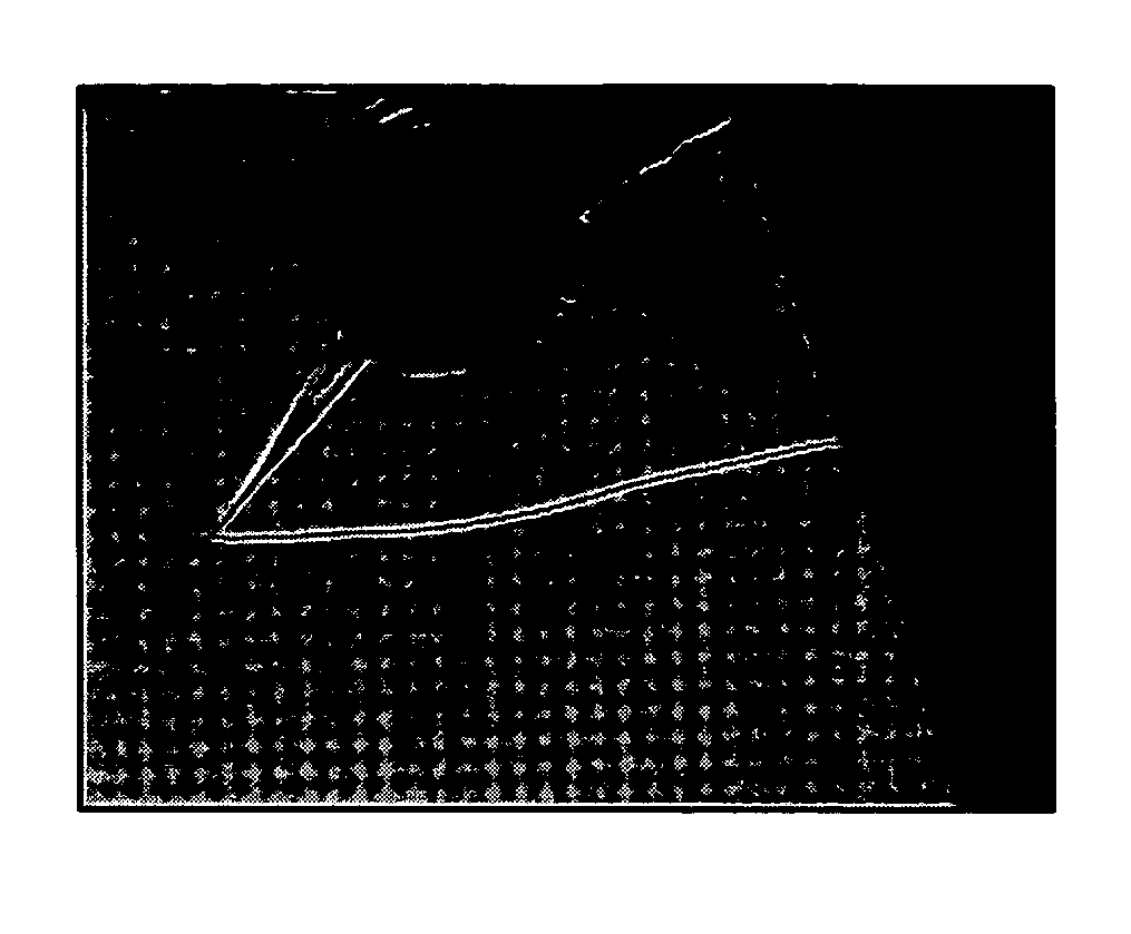
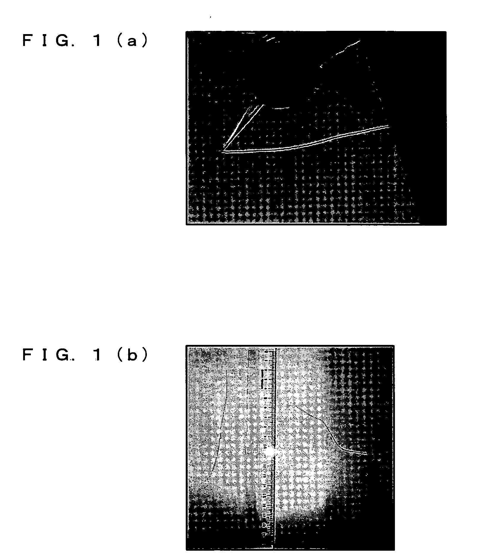
[0061] The present invention is an aggregate of carbon-based microstructures (hereinafter referred to as an “aggregate”), which are aligned in one direction and are assembled together along the direction of alignment. The meaning of an aggregate according to the present invention also includes carbon-based microstructures that are assembled together orthogonal to the direction of alignment. In order to fabricate an aggregate according to the present invention, a multiplicity of carbon-based microstructures is formed on a substrate by being aligned in a direction substantially perpendicular to the substrate, and at least one of the carbon-based microstructures is pulled out. The following describes this in detail.

[0062] [Carbon-Based Microstructures]

[0063] Carbon-based microstructures are nanoscale str...


PUM

PropertyMeasurementUnit
lengthaaaaaaaaaa
lengthaaaaaaaaaa
lengthaaaaaaaaaa

Abstract

An aggregate of carbon-based fine structures in which a plurality of carbon-based fine structures are collected, wherein respective carbon-based fine structures are oriented in the same direction. The above aggregate of carbon-based fine structures is an aggregate of a plurality of carbon-based fine structures in a state they are pulled by one another with strong interaction, and has such a length that allows the improvement of the handleability and workability thereof.

Description

TECHNICAL FIELD [0001] The present invention relates to a carbon-based microstructure array, an aggregate of carbon-based microstructures, use thereof, and a fabrication method thereof. More specifically, the invention relates to an array of carbon-based microstructures, for example, such as carbon nanotubes, and an aggregate of carbon-based microstructures that are held together by strong interactions such as van der Waals forces. The invention also relates to various uses of such array and aggregate of carbon-based microstructures, and a fabrication method thereof. BACKGROUND ART [0002] Carbon nanotubes (hereinafter, “CNTs”), one type of carbon-based micro structure, are carbon material that take the form of a pipe, with a diameter ranging from about 0.5 nm to about 10 nm, and a length of about 1 um. CNTs were first discovered as a new carbon material by S. Iijima of NEC in 1991. There are two types of CNTs: single-walled nanotubes of a single-layer structure, and multi-walled tub...

Claims


Application Information

Patent Timeline
Patent Type & Authority Applications(United States)
IPC IPC(8): C01B31/02C01B31/00B32B9/00B82B1/00D02G3/02D03D15/12
CPCB82B1/00B82Y30/00B82Y40/00C01B31/0233Y10T428/2918C01B31/00Y10S977/742Y10T428/24372Y10T428/292C01B2202/08C01B32/00C01B32/158C01B32/159C01B32/162B82B3/0066
Inventor NAKAYAMA, YOSHIKAZUNOSAKA, TOSHIKAZUSUEKANE, OSAMUNAGASAKA, TAKESHIGOTO, TOSHIKITSUCHIYA, HIROYUKISHIONO, KEISUKE
Owner NIPPON SANSO CORP
Why Eureka
Try Eureka