Al technical title is built by PatSnap Al team. It summarizes the technical point description of the patent document.
A technology of LED light sources and LED components, applied in the direction of light sources, electric light sources, point light sources, etc., can solve problems such as light distribution ghosting, structure and driving power limitations, and light spots, and achieve high insulation safety and unique fixing methods , good optical effect
Active Publication Date: 2013-02-13
JIANGSU HANDSON INTELLIGENT TECH CO LTD
View PDF5 Cites 1 Cited by
Summary
Abstract
Description
Claims
Application Information
AI Technical Summary
This helps you quickly interpret patents by identifying the three key elements:
Problems solved by technology
Method used
Benefits of technology
Problems solved by technology
[0003] At present, the LED AR111 light source on the market solves the shortcomings of the traditional halogen tungsten lamp. It is designed according to the structure and size of the traditional halogen tungsten lamp. The light spot cannot meet the needs of places with high optical requirements, and the electric parameters of the whole light cannot replace AR111 halogen lamps above 75W or MR16, GU10, PAR16 halogen lamps with higher power than 35W due to the limitation of structure and driving power.
In addition, in order to prevent the wires from loosening, the current LED light source module needs an additional power buckle, which leads to more accessories and assembly processes, and affects the appearance of the whole lamp.
Method used
Image
Click on the blue label to locate the original text in one second.
Reading with bidirectional positioning of images and text.
Examples
Embodiment Construction
[0021] The specific implementation manners of the present invention will be further described in detail below in conjunction with the accompanying drawings.
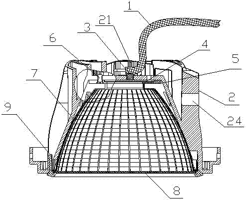
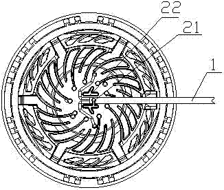
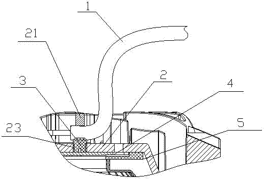
[0022] Such as figure 1 As shown, a light source module using LED as light source, such as AR111 light source module or MR16 light source module, includes: wire 1, radiator 2, plastic screw 3, LED component 4, pressure plate 5, screw 6, reflective cup 7. The light-transmitting plate 8 and the surface cover 9, wherein, the electric wire 1 is fixed on the corresponding fixed structure of the radiator 2 through the plastic screw 3, and the fixed structure is innovatively designed and molded on the radiator 2, which saves a wire buckle and It can effectively prevent the wires from loosening due to external force, and at the same time, the heat sink 2 is designed with ventilation holes to ensure that the heat of the LED is quickly discharged through convection, and the temperature difference between the inside and outside is ...
PUM
Abstract
The invention provides an LED (Light Emitting Diode) light source module and a heat radiator thereof. The LED light source module comprises a wire, a heat radiator, an LED assembly, a pressure plate, a reflection cup, a light transmitting board and a surface cover, wherein the wire is connected to the LED assembly; the light transmitting board is mounted at the port part of the reflection cup and is mounted on the heat radiator through a gland; and a wire fixing structure for fixing the wire is directly formed on the heat radiator by compression molding. The invention also provides the heat radiator on the LED light source module; the wire fixing structure for fixing the wire is directly formed on the heat radiator by compression molding; and the wire is connected to the LED assembly. Due to the adoption of the technical scheme, the wire fixing structure is directly formed on the heat radiator by compression molding; and the LED light source module and the heat radiator thereof have the advantages of novel structure, unique wire fixing mode and convenience for assembly.
Description
technical field [0001] The invention relates to a light source module using a semiconductor light-emitting diode (LED) as a light source, and belongs to the technical field of semiconductor lighting. Background technique [0002] LED AR111, MR16, GU10, and PAR16 light sources are installed in track lights, recessed grille spotlights, hanging wire grille spotlights, recessed ceiling lights, ceiling ceiling lights, etc., which are widely used in shopping malls and large supermarkets , offices, museums, exhibition halls, hotels, high-end residences, etc. are used as key lighting, which can not only brighten the environment, but also beautify the environment, adding color to life. Traditionally commonly used AR111, MR16, GU10, and PAR16 light sources are all halogen lamps, which have high power consumption, low luminous efficiency, high calorific value, short life, and serious pollution in the recycling process. The replacement of LED light source modules has long life (50,000 ...
Claims
Application Information
Patent Timeline
Application Date:The date an application was filed.
Publication Date:The date a patent or application was officially published.
First Publication Date:The earliest publication date of a patent with the same application number.
Issue Date:Publication date of the patent grant document.
PCT Entry Date:The Entry date of PCT National Phase.
Estimated Expiry Date:The statutory expiry date of a patent right according to the Patent Law, and it is the longest term of protection that the patent right can achieve without the termination of the patent right due to other reasons(Term extension factor has been taken into account ).
Invalid Date:Actual expiry date is based on effective date or publication date of legal transaction data of invalid patent.