

Novel ultra wide band Wilkinson power divider
An ultra-broadband and power splitter technology, applied in the field of microwave and millimeter wave power transmission devices, can solve the problems of Wilkinson power splitter performance degradation, thin film resistance calculation deviation, high manufacturing cost, etc., to improve the accuracy of simulation design and production efficiency, eliminate the influence of parasitic effects, and the effect of good input and output matching
Inactive Publication Date: 2013-03-06
黄森
View PDF0 Cites 25 Cited by
- Summary
- Abstract
- Description
- Claims
- Application Information
AI Technical Summary
Problems solved by technology
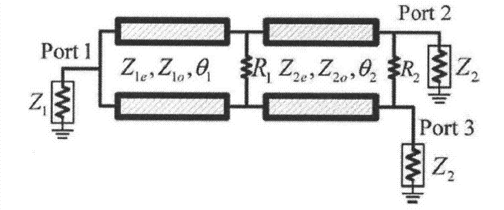
[0004] The disadvantages of the existing Wilkinson power divider: (1) For the Wilkinson power divider in the prior art, in order to make it work in a wider frequency band, generally by increasing the number of isolation resistors and the number of transmission lines series to widen the bandwidth, such as image 3 shown
However, due to its own structural limitations, higher losses will be generated, and at the same time, the additional impact of the distribution parameters of the isolation resistance will be increased, resulting in a large difference between the test results and calculation results, and the performance of the Wilkinson power divider will decline. In addition It is also relatively large
(2) When the Wilkinson power divider is applied to a higher frequency band, the wavelength will be comparable to the size of the isolation resistor, so the distribution parameters at the isolation resistor cannot be ignored, and the distribution parameters are difficult to simulate in the power divider design Prediction, and has a great influence on the final test results
Although thin-film resistors can be used instead of chip resistors in the prior art, the distribution parameters at the thin-film resistors are small, but there is a problem of calculation deviation of the resistance value of thin-film resistors and its manufacturing cost is high
Method used
View moreImage
Smart ImageViewing Examples

Examples
Embodiment 1
[0023] Its structure is as Figure 5 As shown, it is an equal power divider, Figure 6 is the S of the power divider model 11 , S 22 , S 12 , S 23 Schematic diagram of the curve. It can be seen from the graph that the center frequency of the power divider is 4.5GHz, where S 11 ≤-15dB, S 22 ≤-12dB, S 12 ≤0.12dB, S 23 ≤-10dB.
Embodiment 2
[0025] Its structure is as Figure 7 As shown, it is an equal power divider, Figure 8 is the S of the power divider model 11 , S 22 , S 12 , S 23 Schematic diagram of the curve. It can be seen from the graph that the center frequency of the power divider is 4.5GHz, where S 11 ≤-20dB, S 22 ≤-27dB, S 12 ≤0.1dB, S 23 ≤-17.5dB.
Login to View More PUM
 Abstract
The invention discloses a micro-strip Wilkinson power divider capable of working in multiple octave frequency bandwidth, and the power divider consists of transmission lines and a resistor. An input segment and an output segment of the power divider both adopt 50-ohmic transmission lines, namely AB, DE, and DF segments. A beveling technology is applied to B to realize connection between an input end and a BC segment branch line, Klofenstin tapering is applied to the BC segment to realize better transmission characteristic, the CD segment is an impedance matching segment for a BC segment tapered line and the output segment, and the beveling technology is also applied to D to realize better transmission characteristic. The isolating resistor is arranged between the two transmission lines, and the isolation degree of output ends can be regulated through regulating the position of the resistor. By adopting the micro-strip Wilkinson power divider, the input segment and the output segment are well matched, the two output ends are well isolated, the shortcoming that the Wilkinson power divider is influenced by the parasitic effect caused by the isolating resistor is overcome, and the micro-strip Wilkinson power divider is simple in structure, easy to process, very large in operating bandwidth, and low in loss.
Description
technical field [0001] The present invention relates to microwave and millimeter wave power transmission devices, and more specifically, relates to an improved power distribution device. Background technique [0002] A power divider (referred to as a power divider) is a multi-port microwave device that divides the input power into several equal or unequal power outputs. It is used in many circuits such as microwave power sensing, mixer, phase detection, etc. In high-frequency systems such as microwave and millimeter waves, it is necessary to distribute the transmitting or receiving power to each unit in a certain proportion. Therefore, microwave and millimeter wave power dividers have achieved a large number of applications in microwave and millimeter wave components and systems, and are also a key components. There are many realization forms of power divider, such as various 3dB bridge couplers, branch line bridge couplers, ring bridge couplers, Wilkinson power dividers a...
Claims
Login to View More Application Information
Patent Timeline
 Patent Type & AuthorityApplications(China)
IPC IPC(8): H01P5/16
Inventor黄森
Owner黄森