Semi-transparent and semi-reflective liquid-crystal display panel and liquid-crystal display device

A liquid crystal display panel, semi-transparent and semi-reflective technology, applied in instruments, nonlinear optics, optics, etc., can solve the problems of high energy consumption, low power consumption, small ratio, etc., to improve contrast, simplify difficulty, and expand display viewing angle Effect

Inactive Publication Date: 2013-03-20
BOE TECH GRP CO LTD
View PDF4 Cites 7 Cited by
  • Summary
  • Abstract
  • Description
  • Claims
  • Application Information

AI Technical Summary

Problems solved by technology

[0004] The advantage of a transmissive LCD is that it can display bright images in a dark environment, but the disadvantage is that the light that can pass through accounts for a small proportion of the light emitted by the backlight source, and the utilization rate of the backlight source is not high. Increase the brightness of the backlight by a large margin, so the power consumption is high
[0005] The advantage of a reflective LCD is that it can use sunlight or a front light source as a light source, and the power consumption is relatively low, but the disadvantage is that it cannot display images in dark places due to the dependence on external light sources

Method used


Image

  • Semi-transparent and semi-reflective liquid-crystal display panel and liquid-crystal display device
  • Semi-transparent and semi-reflective liquid-crystal display panel and liquid-crystal display device
  • Semi-transparent and semi-reflective liquid-crystal display panel and liquid-crystal display device

Examples


Embodiment Construction

[0049] In order to make the technical problems, technical solutions and advantages to be solved by the present invention clearer, the following will describe in detail with reference to the drawings and specific embodiments.

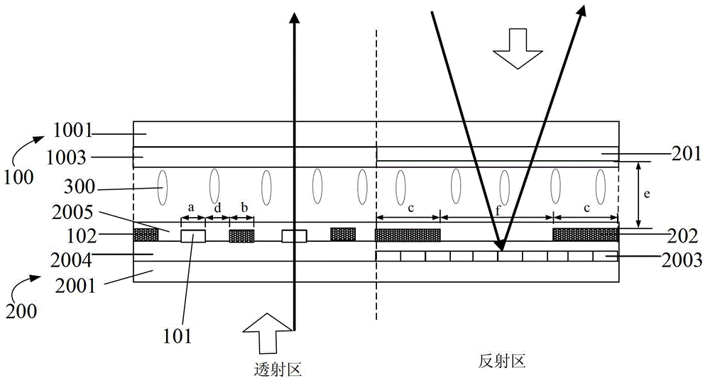
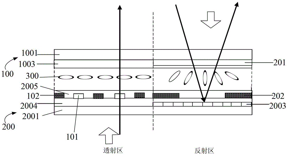
[0050] like Figure 1 to Figure 5 As shown, an embodiment of the present invention provides a transflective liquid crystal display panel, including a first substrate 100, a second substrate 200 disposed opposite to the first substrate 100, and a substrate disposed between the first substrate 100 and the second substrate 200. The liquid crystal layer between them is a positive liquid crystal layer;

[0051] Wherein, the first substrate 100 and the second substrate 200 include several sub-pixels, and each sub-pixel includes a reflection area and a transmission area;

[0052] The thickness of the liquid crystal cell in the reflective area and the transmissive area is equal;

[0053] The part of the second substrate 200 corresponding to the transmissive ar...


PUM

PropertyMeasurementUnit
Box thicknessaaaaaaaaaa
Widthaaaaaaaaaa
Widthaaaaaaaaaa

Abstract

The invention provides a semi-transparent and semi-reflective liquid-crystal display panel and a liquid-crystal display device. The liquid-crystal display panel comprises a first substrate, a second substrate opposite to the first substrate, and a liquid-crystal layer arranged between the first substrate and the second substrate; the liquid crystal of the liquid-crystal layer is positive liquid crystal; the first substrate and the second substrate comprise a plurality of sub-pixels, and each sub-pixel comprises a reflection zone and a transmission zone; the thickness of the liquid-crystal boxes of the reflection zones and the thickness of the liquid-crystal boxes of the transmission zone are equal; a plurality of first common electrodes and first pixel electrodes alternatively arranged at an equal distance are arranged in the part of the second substrate corresponding to the transmission zones; and a second common electrode corresponding to the whole reflection zones is arranged in the part of the first substrate corresponding to the reflection zones, a second pixel electrode corresponding to the reflection zones is arranged in the part of the second substrate corresponding to the reflection zones, and the second pixel electrode comprises at least two shape pixel electrodes arranged at intervals. According to the design of the electrode structure in the transmission zones and the reflection zones, the display effect of semi-transmission and semi-reflection is realized; a display visual angle is enlarged, a contrast ratio is improved; and the structure of a single-box thickness is realized.

Description

technical field [0001] The invention relates to the field of liquid crystal display technology, in particular to a transflective liquid crystal display panel and a liquid crystal display device. Background technique [0002] A liquid crystal display panel is generally formed by pairing a color filter substrate and an array substrate, and a liquid crystal layer is encapsulated in the space between the two substrates. Since the liquid crystal molecules themselves do not emit light, the display needs a light source to display images. According to the type of light source used, liquid crystal displays can be divided into transmissive, reflective and transflective. [0003] Among them, the transmissive liquid crystal display mainly uses the backlight as the light source, and the backlight is arranged behind the liquid crystal panel, and the pixel electrodes on the array substrate are transparent electrodes as the transmission area, which is beneficial for the light of the backlig...

Claims


Application Information

Patent Timeline
IPC IPC(8): G02F1/1343G02F1/1335G02F1/1333
CPCG02F2001/133742G02F1/134309G02F2001/134381G02F1/134363G02F1/133555G02F1/133742G02F1/134381
Inventor 谢畅
Owner BOE TECH GRP CO LTD
Why Eureka
Try Eureka