Walking beam reheating furnace

The technology of a stepping heating furnace and a furnace body is applied in the field of steel rolling equipment, which can solve the problems of poor slag removal effect, damage to the slag scraper, water sealing groove sealing box, and long stroke, so as to achieve good slag removal effect and avoid damage. , The effect of short slag discharge stroke

Active Publication Date: 2013-04-03
LAIWU IRON & STEEL GRP
View PDF6 Cites 4 Cited by
  • Summary
  • Abstract
  • Description
  • Claims
  • Application Information

AI Technical Summary

Problems solved by technology

[0004] However, the above-mentioned slag scraper moves the entire length of the water seal tank relative to the water seal tank every time the slag scraper scrapes, that is, the iron oxide slag in the soaking section 4 needs to be transported to the preheating section 2, which has a long stroke and poor slag removal effect
[0005] In addition, when foreign objects such as sliders, roller heads and furnace wall castables falling off in the furnace fall into the bottom of the water seal tank corresponding to the soaking section 4, causing accumulation and blockage of the water seal tank there, the water seal tank Movement will force the scraper through such buildup or blockage, causing damage to the scraper, water seal or seal box
[0006] Furthermore, when the walking-type heating furnace 1 reversely transports the steel slab in an accident state, the above-mentioned slag scraper does not have the ability to remove slag

Method used


Image

  • Walking beam reheating furnace
  • Walking beam reheating furnace
  • Walking beam reheating furnace

Examples


Embodiment Construction

[0038] The following will clearly and completely describe the technical solutions in the embodiments of the present invention with reference to the accompanying drawings in the embodiments of the present invention. Obviously, the described embodiments are only some, not all, embodiments of the present invention. Based on the embodiments of the present invention, all other embodiments obtained by persons of ordinary skill in the art without making creative efforts belong to the protection scope of the present invention.

[0039] The embodiment of the invention discloses a walking heating furnace, which can discharge the iron oxide slag at the tank bottom corresponding to the water seal tank and the soaking section nearby, and has a good slag removal effect.

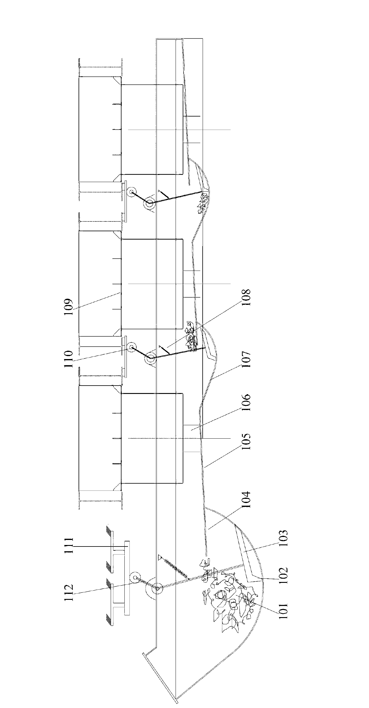
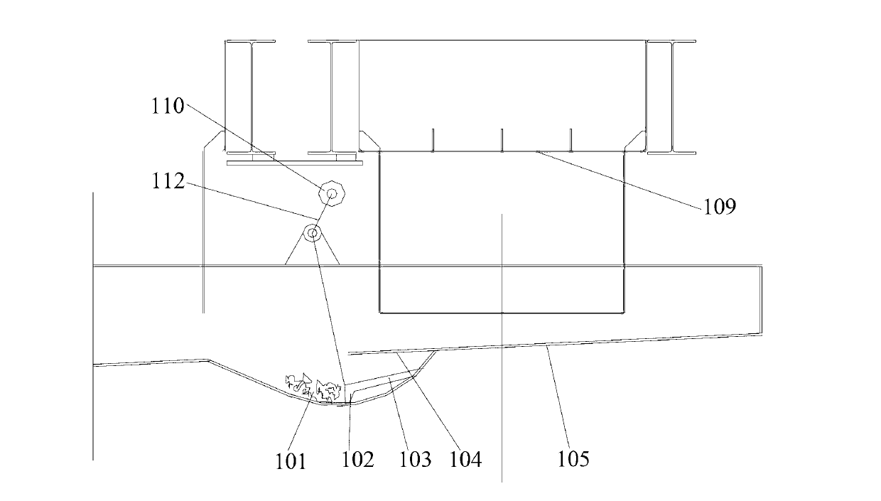
[0040] see Figure 2-Figure 7 The walking heating furnace provided by the embodiment of the present invention includes a furnace body and a water-sealed tank, wherein the bottom of the furnace body is provided with a plura...


PUM


Abstract

The invention discloses a walking beam reheating furnace. The walking beam reheating furnace comprises a furnace body, a water seal tank and seal boxes, wherein the plurality of seal boxes extending out of the furnace body are arranged at the bottom of the furnace body at intervals; the water seal tank is positioned below the furnace body; the lower ends of the seal boxes extend into the water seal tank; the bottom of the water seal tank, corresponding to the soaking section of the walking beam reheating furnace, is an inclined section from the preheating section of walking beam reheating furnace to the soaking section, and a plurality of arc sections are arranged on the inclined section; the walking beam reheating furnace further comprises a V-shaped swing stem hinged with the top of the water seal tank through the bending point, a pulley arranged at one end of the V-shaped swing stem and positioned close to the furnace body and slag pushing pieces fixed at the other end of the V-shaped swing stem and matched with the arc sections; and the opening of the V-shaped swing stem faces to the preheating section and has the angle range of 90 degrees to 180 degrees. By adopting the walking beam reheating furnace, ferric oxide slag at the bottom of the water seal tank, corresponding to the soaking section, can be discharged nearby, so that the slag removal effect is excellent.

Description

technical field [0001] The invention relates to the technical field of steel rolling equipment, and more specifically, relates to a walking heating furnace. Background technique [0002] The walking heating furnace is a continuous heating furnace that relies on the rising, advancing, falling, and retreating actions of the water-cooled metal beam to move the billet forward step by step. see figure 1 , the walking heating furnace 1 can be divided into a preheating section 2, a heating section 3 and a soaking section 4 according to its working process. There are multiple sealing boxes extending out of the furnace body; the water sealing tank is located under the furnace body, the lower end of the above sealing box extends into the water sealing tank, and its end is submerged below the liquid level of the water sealing tank; the moving beam is set In the furnace body, and its lower part is connected with a moving beam column located in a sealed box. When working, the moving b...

Claims


Application Information

Patent Timeline
IPC IPC(8): F27B9/30
Inventor 杨乐彬杨风滨赵勇张丽华赵培胜刘英刚李萍杨文佳
Owner LAIWU IRON & STEEL GRP
Why Eureka
Try Eureka