Oil-containing pollutant treatment system capable of realizing energy-saving control by using PID (Proportion Integration Differentiation) to adjust constant pressure

A pollutant treatment and energy-saving control technology, which is applied in the direction of electric fluid pressure control, pyrolysis sludge treatment, petroleum industry, etc., can solve the problems of intermittent and discontinuous operation, unstable system operation, high safety risk, etc., to reduce Effects of operating cost, realization of resource utilization, and stable system operation

Pending Publication Date: 2018-11-02
大庆百世环保科技开发有限公司
View PDF13 Cites 0 Cited by
  • Summary
  • Abstract
  • Description
  • Claims
  • Application Information

AI Technical Summary

Problems solved by technology

Among them, sludge pyrolysis has been implemented worldwide. The current pollutant-containing treatment system has defects such as intermittent and discontinuous operation, low efficiency, high safety risks, high energy consumption, and unstable system operation.

Method used


Image

  • Oil-containing pollutant treatment system capable of realizing energy-saving control by using PID (Proportion Integration Differentiation) to adjust constant pressure
  • Oil-containing pollutant treatment system capable of realizing energy-saving control by using PID (Proportion Integration Differentiation) to adjust constant pressure
  • Oil-containing pollutant treatment system capable of realizing energy-saving control by using PID (Proportion Integration Differentiation) to adjust constant pressure

Examples


Embodiment 1

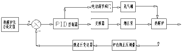
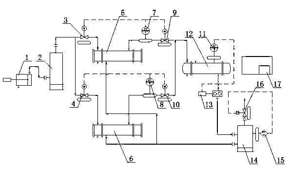
[0017] refer to Figure 1-3 , an oily pollutant treatment system that realizes energy-saving control through PID regulation and constant pressure, including a nitrogen generator 1, a nitrogen tank 2, a first electric regulating valve 3, a second electric regulating valve 4, a third electric regulating valve 9, and a second electric regulating valve. Four electric regulating valves 10, the first pyrolysis furnace 5, the second pyrolysis furnace 6, the first differential pressure transmitter 7, the second differential pressure transmitter 8, the third differential pressure transmitter 11, The fourth differential pressure transmitter 15, buffer tank group 12, booster pump 13, non-condensable gas buffer tank 14, electric switch valve 16 and a PID controller 17; the nitrogen generator 1 passes through the pipeline and the nitrogen tank 2 connection, the nitrogen tank 2 is connected with the first pyrolysis furnace 5 and the second pyrolysis furnace 6 through the pipeline, and the f...


PUM


Abstract

The invention belongs to the technical field of energy-saving and environment-friendly equipment and particularly relates to an oil-containing pollutant treatment system capable of realizing energy-saving control by using PID (Proportion Integration Differentiation) to adjust constant pressure. The oil-containing pollutant treatment system comprises a nitrogen making machine, a nitrogen tank, a first electric adjusting valve, a second electric adjusting valve, a third electric adjusting valve, a fourth electric adjusting valve, a first pyrolyzing furnace, a second pyrolyzing furnace, a first micro-differential-pressure transmitter, a second micro-differential-pressure transmitter, a third micro-differential-pressure transmitter, a fourth micro-differential-pressure transmitter, a bufferingtank group, a boosting pump, a noncondensable-gas buffering tank, an electric switch valve and a PID controller. The oil-containing pollutant treatment system has the beneficial effects that after high-temperature anaerobic reaction of oil-containing pollutant particles, water, oil or organic matters such as polyaromatic hydrocarbon are phase-changed to be vaporized so as to be separated from solids, and solid-phase slags are treated by a closed dry type deslagging technology; gases failed to be condensed by the oil gas are conveyed into the pyrolyzing furnace for environment-friendly reburning after being pressure-stabilized by the boosting pump; the energy consumption can be reduced, the efficiency can be improved, the safety risk can be reduced and the operation is reliable.

Description

technical field [0001] The invention belongs to the technical field of energy-saving and environment-friendly equipment, and in particular relates to an oily pollutant treatment system that realizes energy-saving control through PID regulation and constant pressure. Background technique [0002] Oily pollutants are a kind of solid-liquid mixed waste rich in mineral oil produced in the process of petroleum exploration, exploitation, storage, transportation and refining. Whether oily pollutants enter the soil, oceans, or lakes, they will cause serious pollution to the ecological environment or water sources, and effective and sustainable governance is urgently needed. Among them, sludge pyrolysis has been implemented worldwide. The current pollutant-containing treatment system has defects such as intermittent and discontinuous operation, low efficiency, high safety risks, high energy consumption, and unstable system operation. Therefore, it is necessary to design a high-effic...

Claims


Application Information

Patent Timeline
Patent Type & Authority Applications(China)
IPC IPC(8): C02F11/10C10B57/04G05D16/20
CPCG05D16/20C10B57/045C02F11/10Y02W10/40
Inventor 路学喜李继凤李海燕王亚娟
Owner 大庆百世环保科技开发有限公司
Why Eureka
Try Eureka