Ultra-clean treatment system and ultra-clean treatment method for VOCs in coking plant chemical industry product recovery area

A treatment system and treatment method technology, which is applied in the field of VOCs ultra-clean treatment system in the chemical production recovery area of ​​coking plants, can solve the problems of complex process flow, small scope of application, high investment cost, etc., and achieve simple process flow and no secondary pollution , the effect of low investment

Pending Publication Date: 2020-01-17
MCC CAPITAL ENGINEERING & RESEARCH
View PDF9 Cites 0 Cited by
  • Summary
  • Abstract
  • Description
  • Claims
  • Application Information

AI Technical Summary

Problems solved by technology

However, the cooling and condensation recovery method is only suitable for working conditions with high VOCs concentration and small smoke volume, and its scope of application is small; through condensation and then combustion, the energy consumption is very large and the cost is high; in addition, coking VOCs release gas also contains a certain concentration H 2 S, produces SO by combustion 2 , will cause secondary pollution
[0006] In view of the shortcomings of the existing VOCs treatment technology in the chemical production and recovery area of ​​coking plants, there are complex processes, high investment costs, high energy consumption, large floor area, and secondary pollution. It is urgent to develop another process that is simple, efficient, and efficient. Low operating cost, no secondary pollution, and ultra-clean VOCs treatment technology can be realized

Method used


Image

  • Ultra-clean treatment system and ultra-clean treatment method for VOCs in coking plant chemical industry product recovery area
  • Ultra-clean treatment system and ultra-clean treatment method for VOCs in coking plant chemical industry product recovery area
  • Ultra-clean treatment system and ultra-clean treatment method for VOCs in coking plant chemical industry product recovery area

Examples


Embodiment Construction

[0079] In order to illustrate the present invention more clearly, the present invention will be further described below in conjunction with preferred embodiments. Those skilled in the art should understand that the content specifically described below is illustrative rather than restrictive, and should not limit the protection scope of the present invention.

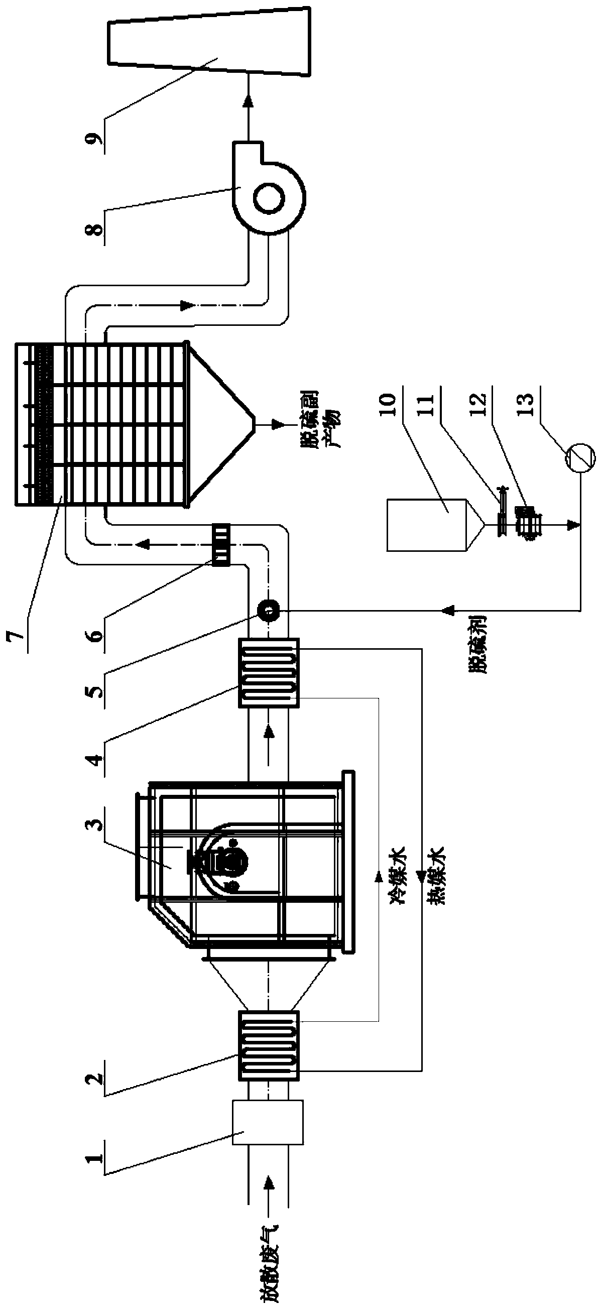
[0080] The present invention provides a preferred embodiment, such as figure 1 As shown, a VOCs ultra-clean treatment system in the chemical production recovery area of ​​a coking plant includes sequentially connected: buffer tank 1, first gas-liquid heat exchanger 2, combustion furnace 3, second gas-liquid heat exchanger 4, desulfurization device, Bag filter 7, induced draft fan 8 and chimney 9.

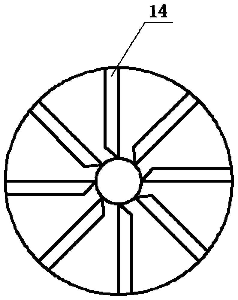
[0081] The desulfurization device includes a desulfurizer nozzle 5 , a desulfurizer storage bin 10 , a manual slide valve 11 , a star feed valve 12 , a conveying fan 13 and a swirl rectifier 6 .

[0082] The desulfurizing ag...


PUM


Abstract

The invention discloses an ultra-clean treatment system and an ultra-clean treatment method for VOCs in a coking plant chemical industry product recovery area. The system comprises a flue gas heatingdevice, a combustion device, a flue gas cooling device, a desulfurization device, a flue gas dust removal device and a flue gas discharge device, wherein the devices are sequentially connected, the flue gas heating device is used for heating diffused waste gas, the combustion device is used for carrying out combustion treatment on the heated diffused waste gas, the flue gas cooling device is usedfor cooling combustion gas from the combustion device, the desulfurization device is used for removing sulfur dioxide from the cooled combustion gas, the flue gas dust removal device is used for removing dust from the desulfurized combustion gas, and the flue gas discharge device is used for discharging the purified gas subjected to dust removal. According to the invention, the method is suitablefor the fields of VOCs treatment of cold drums and desulfurization sections in coking plant chemical industry product recovery areas in iron and steel industry, and has advantages of high purificationefficiency, no secondary pollution, ultra-cleanness, simple process flow, low operation cost and the like.

Description

technical field [0001] The invention relates to the field of VOCs treatment, in particular to a VOCs ultra-clean treatment system and method in a chemical production recovery area of ​​a coking plant. Background technique [0002] Coking plants in the iron and steel industry use coal as raw material to produce coke and coke oven gas through high-temperature dry distillation. The coke produced can be used as fuel for blast furnace smelting, and coke oven gas is recovered and extracted from tar, ammonia and naphthalene through a series of purification sections (chemical production recovery area) , crude benzene, hydrogen sulfide, hydrogen cyanide and other products, and obtain clean coke oven gas. In the chemical production recovery area, there are many equipments involved, and the exhaust gas of various tanks is directly connected to the atmosphere. With the change of medium flow, temperature and pressure, there will be a large amount of VOCs, such as ammonia, tar, naphthalen...

Claims


Application Information

Patent Timeline
Patent Type & Authority Applications(China)
IPC IPC(8): B01D53/83B01D53/50B01D46/02F23G7/06C01D5/02F23J15/02F23J15/06
CPCB01D53/508B01D46/02F23G7/06C01D5/02F23J15/06F23J15/02F23J15/025B01D2251/304B01D2258/0283B01D2257/708F23G2209/14F23G2900/50213F23J2215/20F23J2217/101F23J2219/20Y02A50/20
Inventor 崔岩邱明英朱繁王建华张宇鑫史夏逸任乐史光张传波
Owner MCC CAPITAL ENGINEERING & RESEARCH
Why Eureka
Try Eureka