

Desorption treatment method and device adopting flue gas for indirect heating
A treatment device and treatment method technology, applied in the field of oily pollutant treatment, can solve the problems of difficult control of new pollution sources in soil remediation engineering, insufficient understanding of different pollutants, and poor applicability of equipment, so as to reduce subsequent treatment equipment and avoid solid waste. Particle and dust pollution, effect of reducing input costs
- Summary
- Abstract
- Description
- Claims
- Application Information
AI Technical Summary
Problems solved by technology
Method used
Image

Examples
Embodiment 1
[0019] A kind of desorption treatment method utilizing flue gas indirect heating of the present invention, its steps are as follows:
[0020] a. Crushing: breaking the large oily pollutants into fragments A, the particle size of fragment A is 10mm or 20mm or 30mm;
[0021] b. Hot washing: put the fragment A obtained in step a into 60°C water and stir for 10 minutes, the mass ratio of fragment A to water is 1:10 or 1:15 or 1:20, and oil, water and sludge B are separated to obtain The oil is exported, and the water continues to be recycled;
[0022] c. Thermal desorption: Preheat the oil sludge B obtained in step b at 100°C or 150°C or 200°C, and then gradually raise the temperature to 1000°C at a heating rate of 260°C or 280°C or 300°C / h to obtain oil and gas C and ash D;
[0023] d. Oil and gas treatment: After the solids are removed from the oil and gas C obtained in step c, it is cooled and liquefied at 200°C or 250°C or 300°C, and then the water and heavy oil are separate...
Embodiment 2
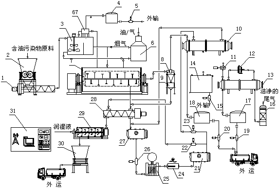
[0026] Such as figure 1As shown, a desorption treatment device using flue gas indirect heating of the present invention is composed of a crusher 2, a thermal desorption device 7 and a separation device. The discharge end of the crusher 2 is connected to a screw conveyor 1 , the screw conveyor 1 is connected to the hot washing device 3, and the crusher 2 combines the functions of stirring and cutting to jointly crush the sludge; at the same time, a reciprocating screen is installed at the outlet to screen debris such as stones with a particle size greater than 20mm, and at the same time Equipped with the function of self-cleaning the inner wall of the cabin, the cleaning inner knife is installed on the blade, so that the sludge stuck on the inner wall can be cleaned, so as to ensure that the motor will not be damaged due to excessive load; and the crusher 1 occupies a small area, with fast processing speed and high efficiency. High, less affected by viscosity, stable treatment ...
PUM
| Property | Measurement | Unit |
|---|---|---|
| Particle size | aaaaa | aaaaa |
Abstract
Description
Claims
Application Information