Double-shaft high-low cycle complex fatigue tester

A fatigue test and fatigue testing machine technology, which is applied in the field of biaxial high and low cycle composite fatigue test devices to achieve the effect of less parts and simple structure

Active Publication Date: 2013-05-01
BEIHANG UNIV
View PDF2 Cites 36 Cited by
  • Summary
  • Abstract
  • Description
  • Claims
  • Application Information

AI Technical Summary

Problems solved by technology

[0007] The purpose of the present invention is to provide a biaxial high-low cycle composite f

Method used


Image

  • Double-shaft high-low cycle complex fatigue tester
  • Double-shaft high-low cycle complex fatigue tester
  • Double-shaft high-low cycle complex fatigue tester

Examples


Example Embodiment

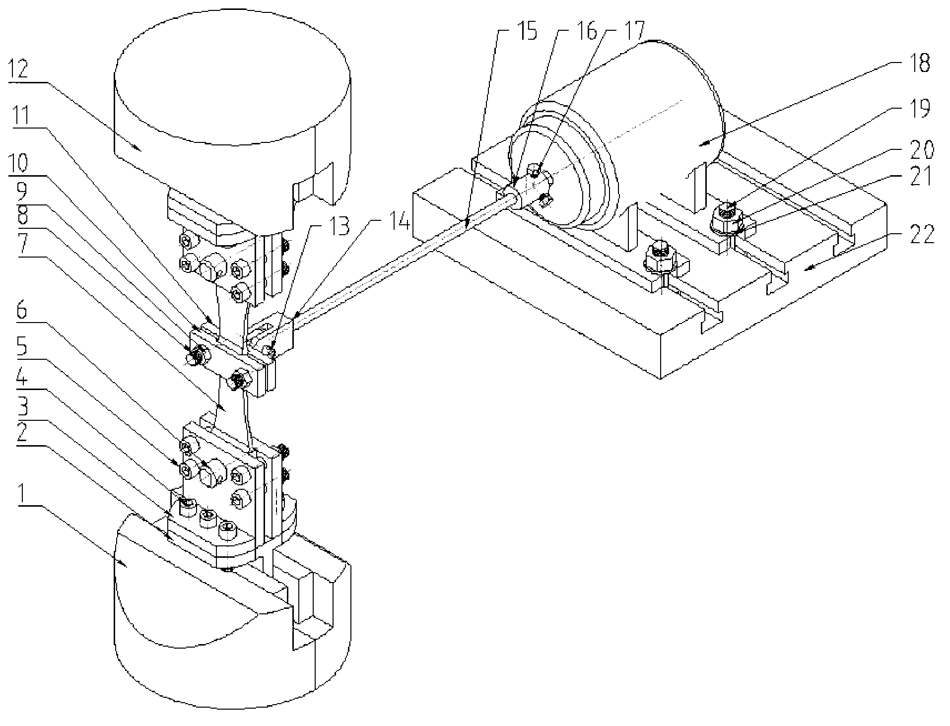
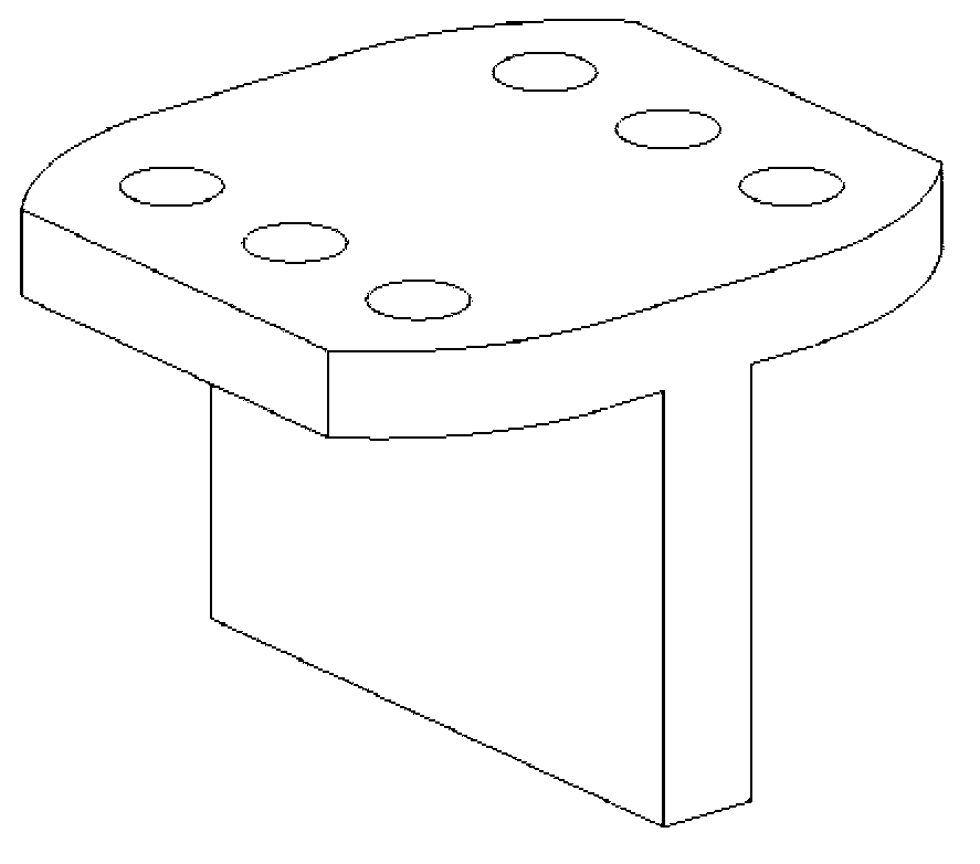
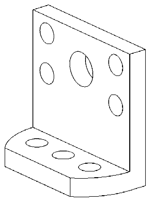
[0044] See figure 1 —— Figure 10 , the present invention is a biaxial high-low cycle composite fatigue test device, the device mainly includes hydraulic fatigue testing machine and upper and lower chucks (1), (12), electromagnetic exciter (18), sample (7) As well as fixtures and positioning connections. The positional connection relationship between them is: the electromagnetic exciter (18) is positioned through the cylindrical connector (16), the connecting rod (15), the U-shaped connector (14) and the middle clamp block in the fixture 2 (11) connection; the middle clamp block 2 (11), the middle clamp block 1 (10) clamp the square mass block convex in the middle of the sample (7) through the inner hexagonal bolt 3 (8) and the outer hexagonal nut 1 (9). platform, the two ends of the sample (7) are connected to the splint (3) in the fixture through the hexagon socket bolt 2 (5) and the large pin (6); the splint (3) is screwed to the flat end of the connector (2) in the fixtu...


PUM


Abstract

A double-shaft high-low cycle complex fatigue tester comprises a hydraulic fatigue tester, an upper clamping head, a lower clamping head, an electromagnetic vibration exciter, a sample, a fixture, and a locating connecting device. The electromagnetic vibration exciter is connected with a middle clamping block 2 in the fixture via a cylindrical connector, a connecting rod and a U-shaped connector in a positioning connecting device; the middle clamping block 2 and a middle clamping block 1 are used for clamping a square mass boss at the middle part of the sample via a connecting piece, and the two ends of the sample are connected with a plywood in the fixture via the connecting piece; the plywood is connected with the connector in the fixture via bolts in the connecting piece; and the vertical ends of the connector are placed in the grooves of the upper clamping head and the lower clamping head of the hydraulic fatigue tester, contacted with the hydraulic fatigue tester, and clamped tightly via the hydraulic pressure of the tester. The tester is simple in structure and convenient to operate, solves the problems of load interference and load coordination in the vertical direction and the horizontal direction during bidirectional loading aiming at the plate-shaped sample, and can be used for simulating fatigue load borne by the blades of the rotor of a gas turbine engine.

Description

technical field [0001] The invention relates to a biaxial high-low cycle compound fatigue test device, which belongs to the field of material and structure fatigue performance test. Background technique [0002] The design of modern gas turbine engines needs to achieve a comprehensive balance between high performance, high reliability, and good economy. Rotor blades of gas turbine engines, such as fans, compressors, and turbine blades, are subjected to large low-frequency centrifugal force loads due to rotation during operation, and are also subjected to high-frequency loads of forced vibration of airflow, which makes high and low in the engine rotor blades. Cyclic composite fatigue failure mode. This means that in order to design a well-performing and reliable engine, it is necessary to improve the fatigue resistance of the components. [0003] Improving the fatigue resistance of components is mainly achieved through the improvement of material properties and structural f...

Claims


Application Information

Patent Timeline
IPC IPC(8): G01N3/32G01N3/10G01M13/00
Inventor 石多奇骆银银杨晓光
Owner BEIHANG UNIV
Why Eureka
Try Eureka