Steel material cutter and locking method of knife head of steel material cutter

A cutting machine and cutter head technology, which is applied in the directions of large fixed members, metal processing machinery parts, metal processing equipment, etc., can solve the problems of many parts, high cost, complex device structure, etc., and achieves few parts, simple structure and low cost. Effect

Inactive Publication Date: 2013-08-21
KEN HLDG CO LTD
View PDF10 Cites 2 Cited by
  • Summary
  • Abstract
  • Description
  • Claims
  • Application Information

AI Technical Summary

Problems solved by technology

[0003] However, the device structure adopted in the prior art is comparatively complicated,

Method used


Image

  • Steel material cutter and locking method of knife head of steel material cutter
  • Steel material cutter and locking method of knife head of steel material cutter
  • Steel material cutter and locking method of knife head of steel material cutter

Examples


Example Embodiment

[0019] Example 1

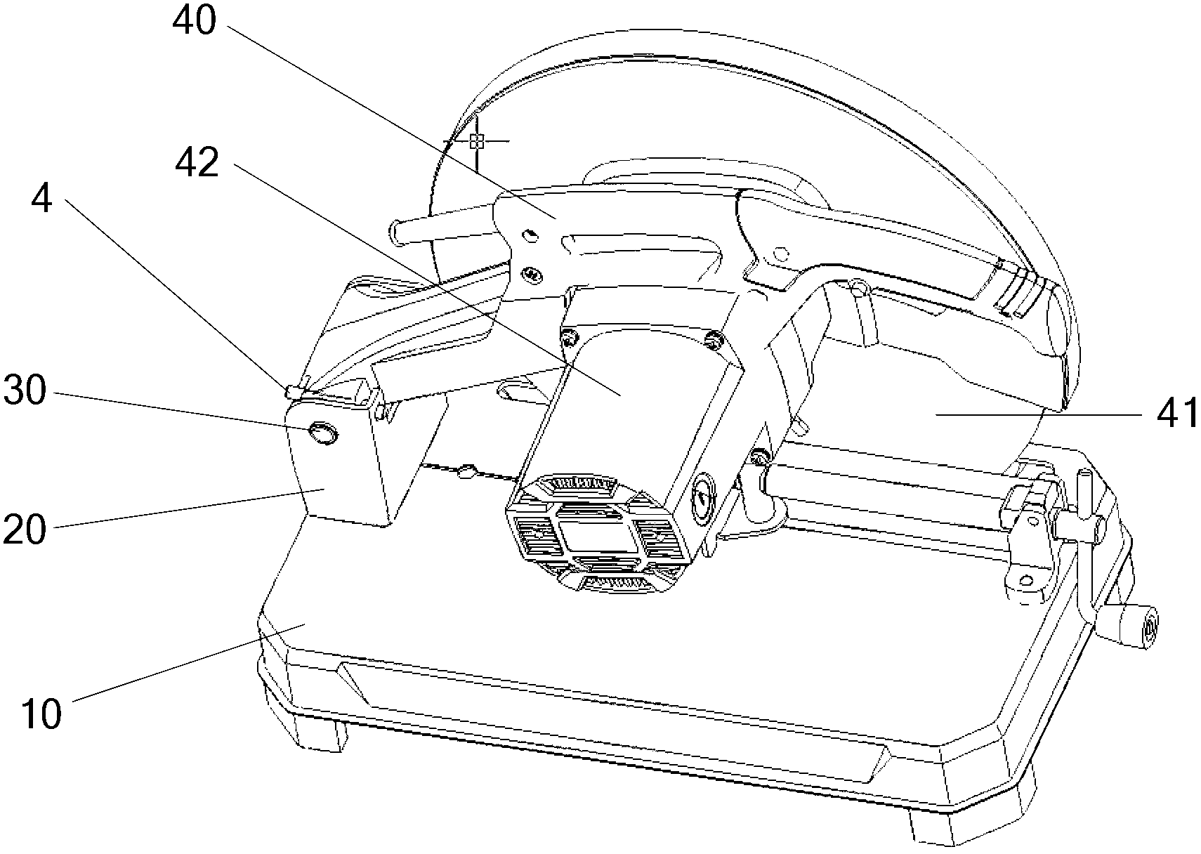
[0020] Please refer to figure 2 and image 3 , the present embodiment provides a method for locking a cutter head of a steel material cutting machine. A steel material cutting machine is provided, and the steel material cutting machine at least includes a cutter head 41 and a bottom plate 10. First, the cutter head 41 is installed on a On the rotating arm 40, the cutter head is circular. When the cutter head 41 is installed, the center of circle of the cutter head 41 is connected with the rotating motor 42 provided on the rotating arm 40, and then a bolt 30 is used to Pass through one end of the rotating arm 40 and a connecting seat 20 fixed on the bottom plate 10, so that the bolt 30 is parallel to the bottom plate 10, and the rotating arm 40 can rotate around the axis of the bolt 30 Rotate to the direction, and then make the cutter head 41 realize the axial rotation around the bolt 30 by the rotation of the rotating arm 40; The rotation position of the...

Example Embodiment

[0026] Example 2

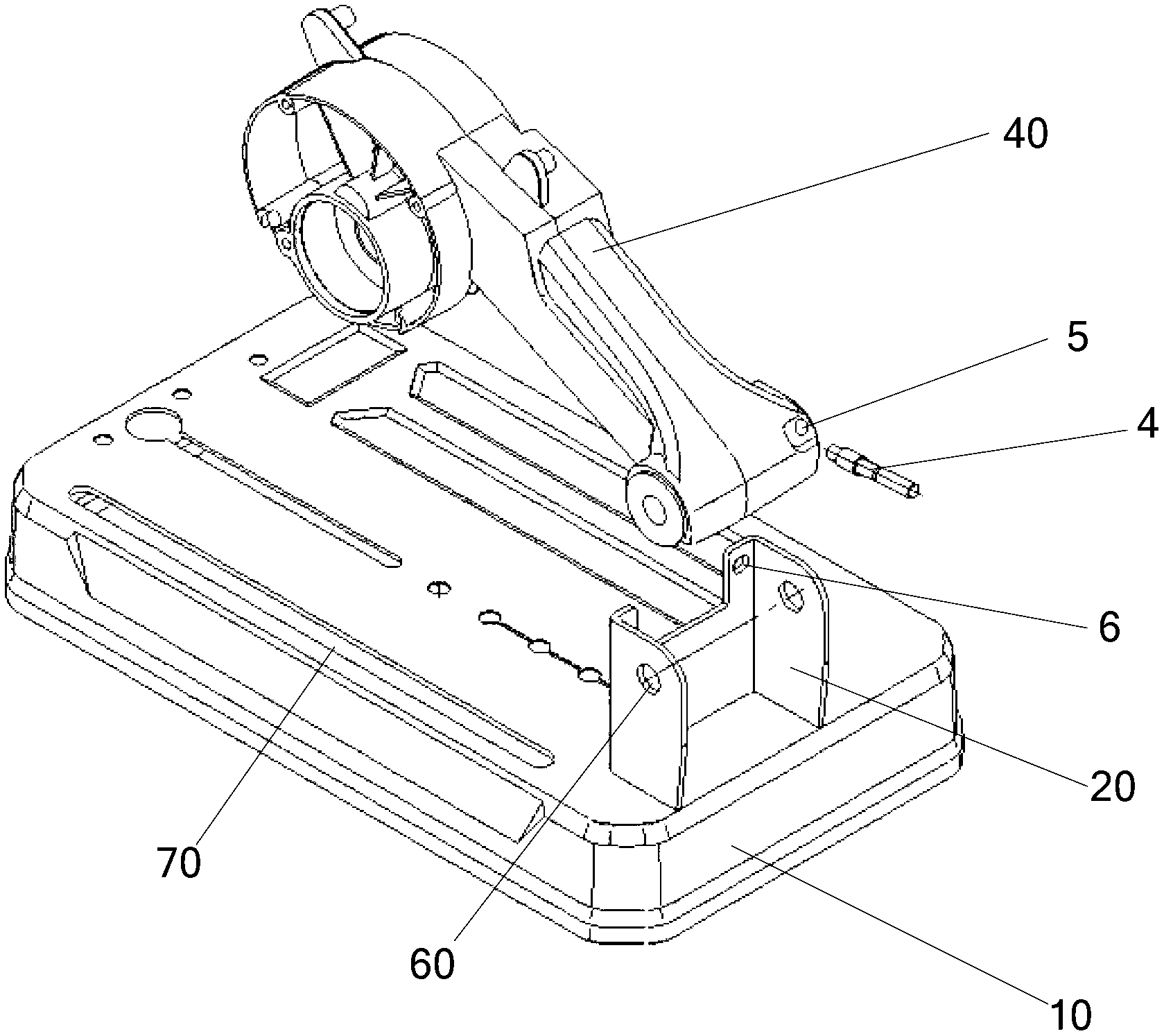
[0027] In this example, please refer to Figure 4 and Figure 5 , the locking bar 4 is arranged parallel to the bolt 30 .

[0028] Please refer to Figure 4 and Figure 5 , The difference between this embodiment and Embodiment 1 is only that when the locking rod 4 passes through the first through hole 5 and the second through hole 6 at the same time, the locking rod 4 is parallel to the latch 30 . This setting is conducive to the stability of the lock bar 4 when locked, the effect is better, and it is not easy to fall off. Please refer to Figure 5 , the connection seat 20 includes two opposite sides and a connecting surface connecting the two sides, pin holes 60 are respectively arranged on the two sides for the shaft pin 60 to pass through, in this embodiment, the second through hole 6 is set On one side, the positions of the first through hole 5 and the second through hole 6 correspond, that is, when the rotating arm 40 is in the locked position, th...


PUM


Abstract

The invention provides a steel material cutter and a locking method of a knife head of the steel material cutter. The steel material cutter at least comprises the knife head and a bottom plate. The locking method of the knife head comprises the steps that first, the knife head is arranged on a rotating arm, the knife head is circular, when the knife head is mounted, the circle center of the knife head is connected with a rotating motor arranged on the rotating arm, an inserting pin is used for respectively penetrating through one end of the rotating arm and a connecting seat fixedly arranged on the bottom plate, so that the inserting pin is parallel to the bottom plate, the rotating arm can rotate around the axis direction of the inserting pin, and accordingly the fact that the knife head rotates around the axis direction of the inserting pin and is used by rotating of the rotating arm is achieved, and when the knife head does not need to be used, a locking rod respectively penetrates through the rotating arm and the connecting seat to fix the rotating position of the rotating arm.

Description

technical field [0001] The invention relates to a locking device, in particular to a steel cutting machine and a method for locking a cutting head thereof. Background technique [0002] In the prior art, the steel machine includes a bottom plate 10, a rotating arm 40, a pivot pin 30 and a connecting portion 20, the connecting portion 20 is fixedly connected to the bottom plate 10, the pivot pin 30 is parallel to the bottom plate 10, and Respectively passing through the connecting part 20 and one end of the rotating arm 40, the power head 40 can rotate around the shaft pin 30, and the locking of the position of the power head of the steel machine is accomplished by a set of locking devices, please refer to figure 1 , the locking device includes a cylindrical pin 1 , a hook 2 and a chain 3 , one end of the cylindrical pin 1 is connected to the chain 3 through the hook 2 , and the other end of the chain 3 is fixedly connected to the bottom plate 10 . In addition, a support sea...

Claims


Application Information

Patent Timeline
IPC IPC(8): B23Q1/26
Inventor 吴明厅应小勇马国刚
Owner KEN HLDG CO LTD
Why Eureka
Try Eureka