Engine with compression ratios variable

A compression ratio, engine technology, applied in engine control, combustion engine, machine/engine, etc., to achieve the effect of less fuel consumption, low emissions, and improved power

Active Publication Date: 2013-05-22
范伟俊
View PDF7 Cites 13 Cited by
  • Summary
  • Abstract
  • Description
  • Claims
  • Application Information

AI Technical Summary

Problems solved by technology

The compression ratio of traditional engines is generally fixed. In recent years, foreign countries have begun to shift the direction of research to engines with variable compression ratios to meet the different requirements of engines for compression ratios under different operating conditions. When the engines are under medium and low loads, In order to improve the emission level of the engine, it is necessary to use a larger compression ratio, and to use a higher boost pressure at high loads, it is necessary to reduce the compression ratio, which can improve the fuel efficiency and output power of the engine. At present, domestic research has begun to Engines with variable compression ratio, but most of them have complex structures and high processing difficulties, which are not convenient for mass production

Method used


Image

  • Engine with compression ratios variable
  • Engine with compression ratios variable
  • Engine with compression ratios variable

Examples


Embodiment 1

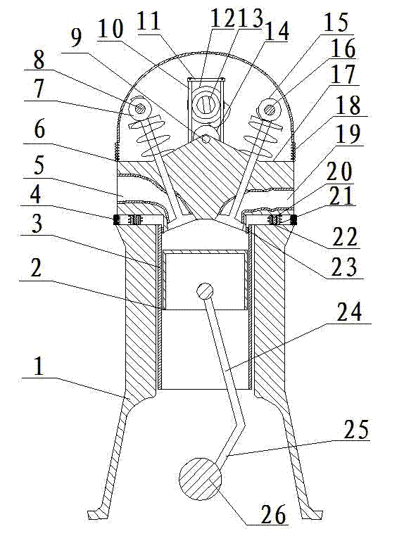
[0032] figure 1 As shown, it is a schematic diagram of the cross-sectional structure of the cylinder head in this embodiment moving to the upper end and the lower end. It can be seen that the engine is cut longitudinally, including the cylinder block 1, the cylinder head 17 and the cylinder head cover 18 located on the cylinder head 17, and the cylinder block 1 A cylinder 3, a piston 2, a connecting rod 24, a crank 25 and a crankshaft 26 are arranged inside.

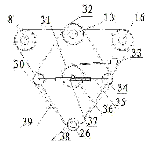
[0033] The center of cylinder head 17 tops is provided with groove, is provided with wheel 14 in the groove, and wheel 14 center is perforated and is connected with cross pin 9 by bearing, and cross pin 9 two ends link to each other with groove inner side; Cam 12, cam 12 is fixedly connected on the camshaft 13, and one end of the camshaft 13 is provided with a camshaft sprocket 32, and the camshaft sprocket 32 ​​is driven by the crankshaft sprocket 38 at one end of the crankshaft 26 through a transmission mechanism, and...

Embodiment 2

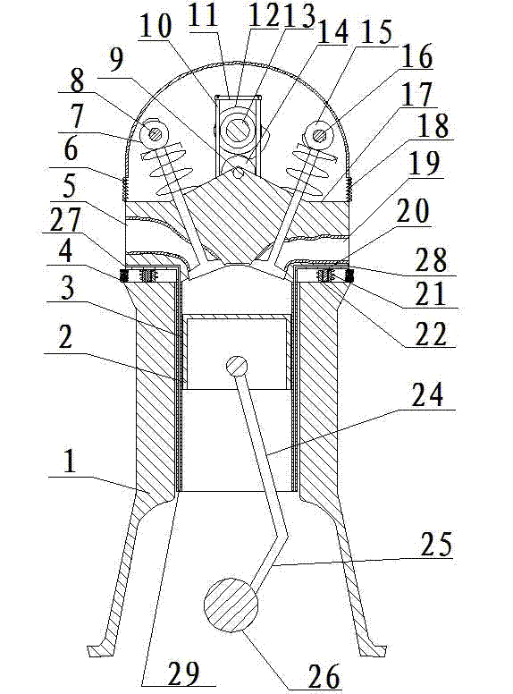
[0043] figure 2 As shown, it is a schematic diagram of the cross-sectional structure of the cylinder head in this embodiment moving to the upper end and the lower end. It can be seen that the engine is cut longitudinally, including the cylinder block 1, the cylinder head 17 and the cylinder head cover 18 located on the cylinder head 17, and the cylinder block 1 A cylinder 3, a piston 2, a connecting rod 24, a crank 25 and a crankshaft 26 are arranged inside.

[0044] The center of cylinder head 17 tops is provided with groove, is provided with wheel 14 in the groove, and wheel 14 center is perforated and is connected with cross pin 9 by bearing, and cross pin 9 two ends are connected with groove inner side; Cam 12, cam 12 is fixedly connected on the camshaft 13, and one end of the camshaft 13 is provided with a camshaft sprocket 32, and the camshaft sprocket 32 ​​is driven by the crankshaft sprocket 38 at one end of the crankshaft 26 through a transmission mechanism, and the ...


PUM


Abstract

The invention discloses an engine with compression ratios variable. The engine with the compression ratios changeable comprises a cylinder body, a cylinder cover, a cylinder cover cap, a cylinder barrel, a bent axle, a connection rod and a piston, and is characterized in that a groove is arranged at the center of the top end of the cylinder cover, and a wheel is arranged inside the groove. A cam is arranged on the upper portion of the wheel and is fixedly connected on a cam shaft, wherein one end of the cam shaft is provided with a cam shaft gear, the cam shaft gear is driven by a bent axle gear at one end of the bent axle through a transmission mechanism, and the transmission mechanism can ensure changes of relative angles between the cam and the bent wheel. The periphery of the upper edge of the cylinder cover is connected with the periphery of the lower edge of the cylinder cover cap through an upper rubber boot, and the periphery of the lower edge of the cylinder cover is connected with the periphery of the upper edge of the cylinder body through a lower rubber boot. Two pins are symmetrically arranged on the left lower side and the right lower side of the cylinder cover. Sleeves are arranged on the left upper side and the right upper side of the cylinder body and match with the pins in a sliding mode. Springs are sleeved outside the pins and the sleeves. The engine with the compression ratios variable can change the compression ratios of the engine, effectively improve power of the engine and improve fuel oil economical efficiency.

Description

Technical field [0001] The present invention involves an engine, especially a transformer -perable ratio engine. Background technique [0002] The compression ratio of the engine refers to the ratio of the cylinder volume between the cylinder volume when the piston movement is from the downtown to the upper stop point.The compression ratio of traditional engines is generally fixed. In recent years, foreign countries have begun to turn the research direction to the engine with a transformer ratio to adapt to the different requirements of the compression ratio when the engine is in different operating conditions.In order to improve the level of the engine, a large compression ratio is needed, and higher pressure pressure pressure is used when high load, which needs to reduce the compression ratio.The engine of the transformer ratio, but most of the structure is complicated, the processing is difficult, and it is not convenient to put into production in large quantities. Invention...

Claims


Application Information

Patent Timeline
Patent Type & Authority Applications(China)
IPC IPC(8): F02B75/04F02D15/04
CPCF02D15/04F02B75/04F02B75/041Y02T10/12
Inventor 范伟俊
Owner 范伟俊
Why Eureka
Try Eureka