Improved variable compression ratio piston for internal combustion engine

An improved, compression ratio technology, used in pistons, mechanical equipment, engine components, etc., can solve the problems of rapid piston reset, rapid changes in stiffness, short service life, etc., to overcome the slow response speed of load changes. Effect

Inactive Publication Date: 2011-12-07
WUHAN UNIV OF TECH
View PDF12 Cites 3 Cited by
  • Summary
  • Abstract
  • Description
  • Claims
  • Application Information

AI Technical Summary

Problems solved by technology

For the hydraulic deformation mechanism, due to the high pressure during the actual combustion of the engine, this puts forward high requirements for the hydraulic mechanism and its control system. The existing hydraulic mechanism has complex structures, poor high-temperature sealing performance, and short service life. Defects such as slow response speed and other defects make it difficult to quickly reset the piston after deformation
As far as the elastic deformation element is concerned, the existing elastic deformation elements often use ordinary compression springs, and the stiffness of ordinary compression springs cannot change rapidly with the load conditions in the cylinder, and there is a gap between the upper and lower parts of the piston. Arrangi

Method used


Image

  • Improved variable compression ratio piston for internal combustion engine
  • Improved variable compression ratio piston for internal combustion engine
  • Improved variable compression ratio piston for internal combustion engine

Examples


Embodiment Construction

[0027] The present invention will be further described in detail below in conjunction with the accompanying drawings and specific embodiments.

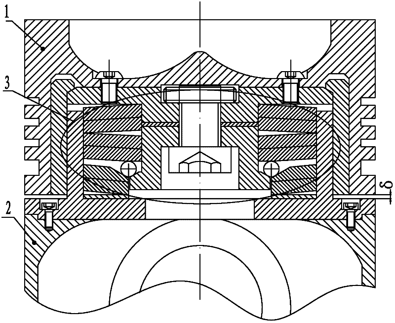
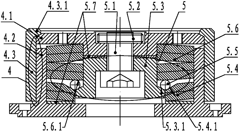
[0028] The improved variable compression ratio piston of the internal combustion engine shown in the figure includes a piston crown 1 and a piston skirt 2, and a compression ratio adjusting device 3 is arranged between the piston crown 1 and the piston skirt 2. The compression ratio adjusting device 3 includes an adjusting device housing 4 and a mechanical elastic deformation mechanism 5 .

[0029] The regulating device housing 4 is composed of a circular pressure plate 4.1 fixedly connected to the bottom surface of the piston top 1 by a locking screw, an inner cylinder located below the circular pressure plate 4.1 and fixedly connected to the top surface of the piston skirt 2 by a locking screw 4.2, and an outer cylinder 4.3 that is threadedly connected with the inner cylinder 4.2. An inner stop ring 4.3.1 is provided at the mouth o...


PUM

PropertyMeasurementUnit
Horizontal inclinationaaaaaaaaaa

Abstract

The invention discloses an improved variable compression ratio piston for an internal combustion engine, which relates to an optimization design for a variable compression ratio piston with the publication number of CN101900056A. A mechanically-elastic deformation mechanism in a compression ration adjustment device comprises a circular inclined plane driving disk which is arranged at the central position of the mechanism and an annular incline plane supporting ring which is arranged on the outer side of the circular inclined plane driving disk, wherein steel balls are uniformly distributed ina V-shaped ring slot which is enclosed by the supporting inclined plane of the annular inclined plane supporting ring and the driving incline plane of the circular inclined plane driving disk; elastic reset elements are arranged on the upper sides of the steel balls; and the bottom surfaces of the elastic reset elements are pressed against the steel balls. Compared with a mechanically-elastic deformation mechanism which is not optimized, the mechanically-elastic deformation mechanism eliminates a spring seat disc and can make the elastic reset elements positioned in a force arm alteration state when the steel balls are moved, so that the requirements of high rigidity before the application of pre-tightening force and low rigidity after the application of the pre-tightening force of the mechanically-elastic deformation mechanism can be better met. The piston has a simpler structure and lower cost, is more reliably operated, and has the compression ratio which can also be subjected to quick adaptability alteration along with the working condition of an engine.

Description

technical field [0001] The invention relates to the optimized design of the piston with the publication number CN101900056A and the title of the invention is variable compression ratio piston of internal combustion engine, and specifically refers to an improved variable compression ratio piston of internal combustion engine. Background technique [0002] The cylinder compression ratio has a great influence on the performance of the internal combustion engine. Variable compression ratio technology means that the engine has a higher compression ratio under low-load conditions, and can control the excessively high gas pressure in the cylinder by adjusting the compression ratio under high-load conditions. At present, according to the response speed of the compression ratio changing with the engine operating conditions, the variable compression ratio technology mainly falls into the following two categories: [0003] 1. The compression ratio changes slowly with the engine operat...

Claims


Application Information

Patent Timeline
IPC IPC(8): F02F3/00F02D15/04
Inventor 董健李格升潘志翔郑亮阮见明周越欧阳林
Owner WUHAN UNIV OF TECH
Why Eureka
Try Eureka