
Lens Driving Device

a driving device and lens module technology, applied in the field of lens module, can solve the problems of delayed reset, increased cost of lens module, and difficulty in realizing the miniaturization of camera modul

Active Publication Date: 2016-06-09
AAC OPTICS (CHANGZHOU) CO LTD
View PDF7 Cites 44 Cited by
  • Summary
  • Abstract
  • Description
  • Claims
  • Application Information

AI Technical Summary

Benefits of technology

The present invention provides a lens module with optical image stabilization (OIS) function against shaking. However, current technology requires the use of a hall sensor which increases the cost of the lens module and makes it difficult to miniaturize the camera module. Additionally, the recovery action of the lens in situ is accomplished by a control circuit, which delays the reset and lowers reliability. To achieve automatic focusing (AF) function, the OIS lens module must also supply AF coil with appropriate current coil, which further complicates the assembly process and lowers production efficiency. The technical effects of the invention are to provide a cost-effective, miniaturizable, reliable, and efficient lens module with OIS function and AF function.

Problems solved by technology

Consequent question is, hall sensor will cause the increase in the cost of lens module, and the camera module structure is complex, hence it is difficult to realize the miniaturization of camera module.
In addition, the recovery action of lens in situ is accomplished by control circuit, hence the reset will be delayed, and the reliability is low.
However, it is extremely difficult to add suspension wire in the process of cascade and combination of multiple parts, therefore increasing the assembly difficulty of camera module, and the production efficiency is low.

Method used


Image

  • Lens Driving Device
  • Lens Driving Device
  • Lens Driving Device

Examples


Embodiment Construction

[0016]The present invention will hereinafter be described in detail with reference to an exemplary embodiment. It should be understood the specific embodiment described hereby is only to explain this disclosure, not intended to limit this disclosure.

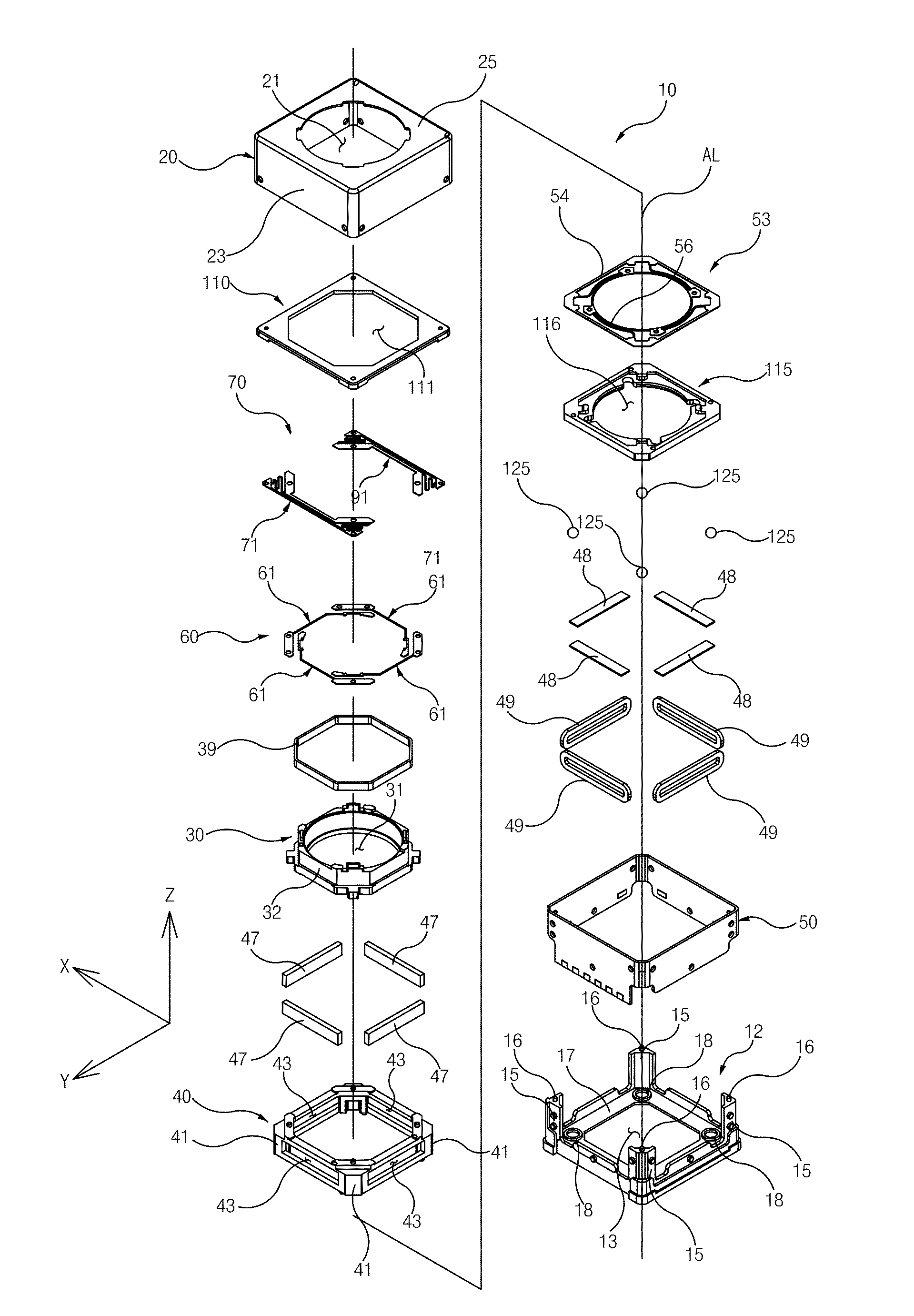
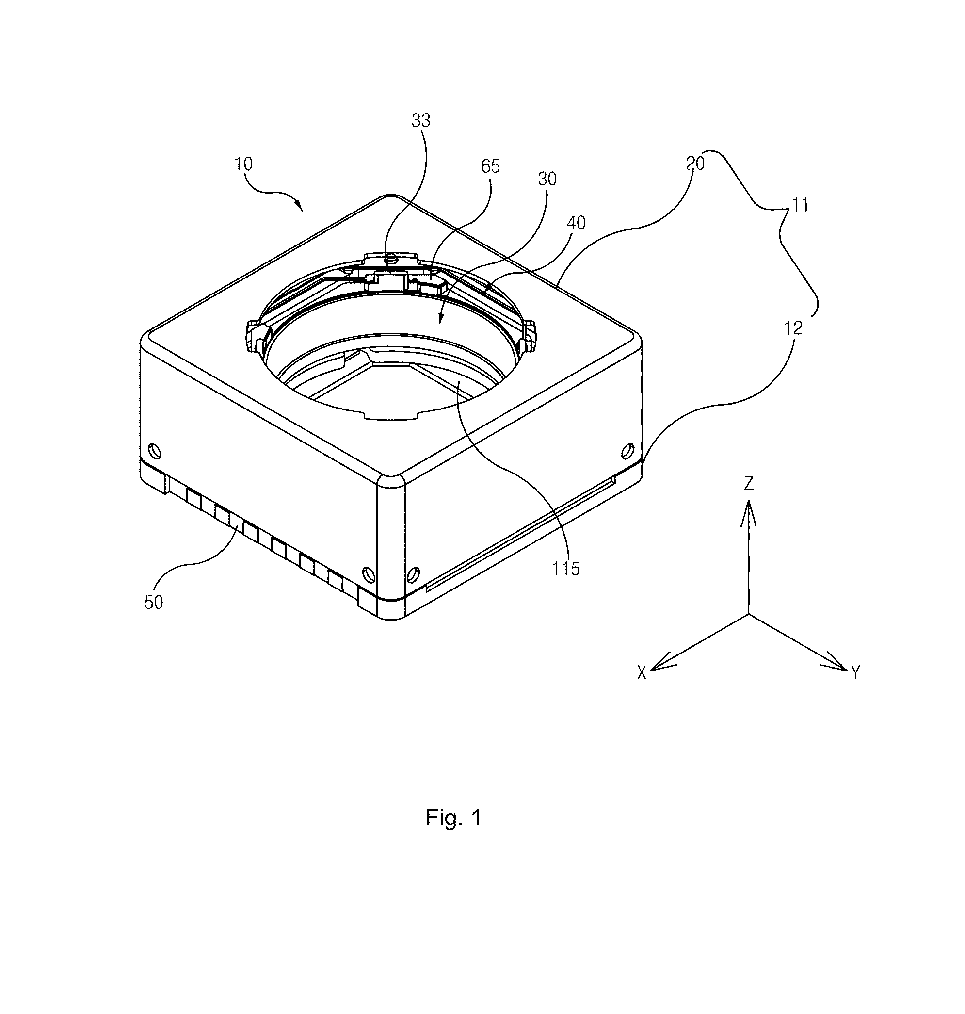
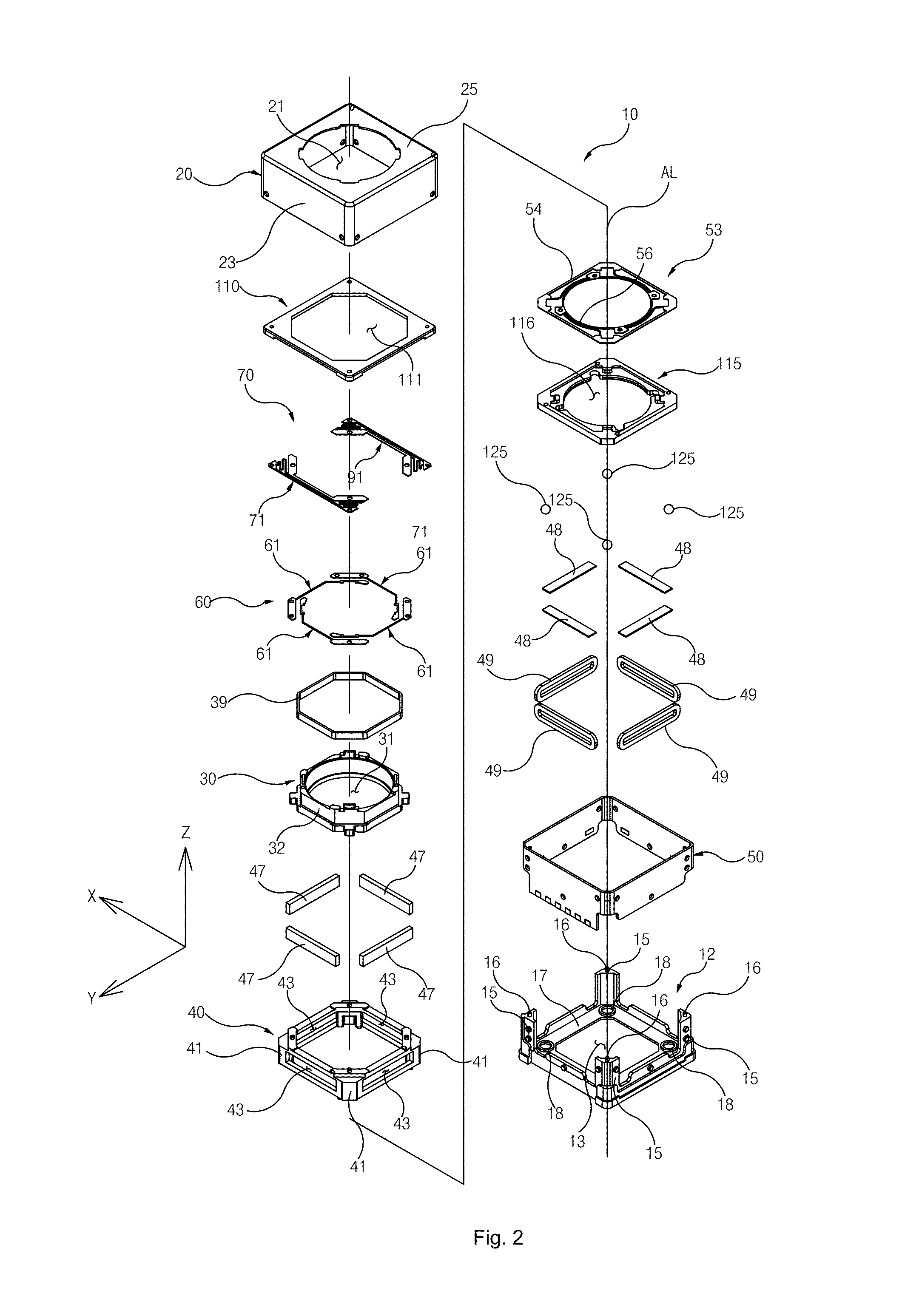
[0017]Referring to FIGS. 1-5, a lens driving device 10 provided by the invention that can be applied in smartphones, laptop computers has AF (auto focusing) and OIS (optical image stabilization) functions. The lens driving device 10 includes a housing 11, a lens barrel 30, an anti-shake carrier 40, a permanent magnet 47, a magnet yoke 48, a focusing coil 39, an anti-shake coil 49, a flexible printed circuit board 50, a upper gasket 110, a lower gasket 115, a lower spring 53, an upper spring 60, an anti-shake spring 70 and a bearing steel ball 125.

[0018]The housing 11 includes a base 12 and a cover body 20 assembled with the base 12 to form an receiving space. The base 12 is one rectangular box body structure and includes a bottom surface...


PUM


Abstract

A lens driving device is disclosed. The lens driving device includes a housing including a base, and a cover body forming a receiving space together with the base; a lens barrel assembled inside the housing and moveable along an optical axis of the lens barrel; an anti-shake carrier assembled inside the housing for suspending the lens barrel along the optical axis; an anti-shake spring having one end thereof fixed to the housing, and another end fixed on the anti-shake carrier; a plurality of bearing steel balls provided between the base and the anti-shake carrier for reducing friction force when the anti-shake carrier moves perpendicular to the optical axis; wherein the anti-shake carrier depends on elastic force of the anti-shake spring when it moves perpendicular to the optical axis, and the anti-shake carrier will return to an initial position.

Description

FIELD OF THE INVENTION[0001]The present invention is related to a type of lens module of camera, especially to a lens driving device having optical image stabilizing (OIS) function against the dithering images caused by shaking.DESCRIPTION OF RELATED ART[0002]Recently, portable terminals similar to smart phones and tablets are equipped with high-performance camera modules in addition to portable camera. High-performance lens module configured in the portable terminal generally has the functions of auto focusing and optical image stabilization. The function of optical image stabilization (OIS) can reduce the image shaking caused by external vibration or the trembling of user's hands. Optical anti-shaking function is divided into the lens shift type by which the lens moves along direction perpendicular to optical axis of camera and image sensor shift type by that the image sensor moves along the direction perpendicular to optional axis of lens. Normally, the portable terminal is equip...

Claims


Application Information

Patent Timeline
Patent Type & Authority Applications(United States)
IPC IPC(8): G02B27/64G02B7/08G02B7/02
CPCG02B27/646G02B7/08G02B7/026G02B7/09G03B5/00G03B13/36G03B5/04G03B30/00G03B2205/0069G03B2217/007
Inventor HEE, SUL HYUNYUE, YANG DEAJIN, KIM YOUNG
Owner AAC OPTICS (CHANGZHOU) CO LTD
Learn More