Heat conduction coefficient and contact thermal resistance testing device

A technology of contact thermal resistance and thermal conductivity, which is applied in the field of devices for accurately measuring material thermal conductivity and contact thermal resistance, can solve the problems of temperature measurement uncertainty error, difficult interface contact thermal resistance measurement accuracy, etc., to improve test accuracy, Effects of reducing heat loss and eliminating uncertainty errors

Active Publication Date: 2012-11-28
NANJING UNIV OF SCI & TECH
View PDF3 Cites 45 Cited by
  • Summary
  • Abstract
  • Description
  • Claims
  • Application Information

AI Technical Summary

Problems solved by technology

Most of the steady-state contact thermal resistance test methods are similar to the test standard equipment of the American National Standard ASTM D5470-06, but many documents point out tha

Method used


Image

  • Heat conduction coefficient and contact thermal resistance testing device
  • Heat conduction coefficient and contact thermal resistance testing device
  • Heat conduction coefficient and contact thermal resistance testing device

Examples


Embodiment Construction

[0011] The present invention will be described in further detail below in conjunction with the accompanying drawings.

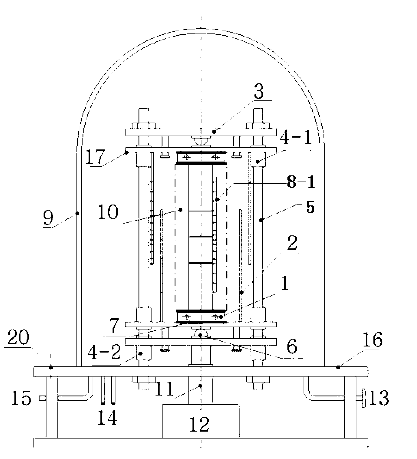
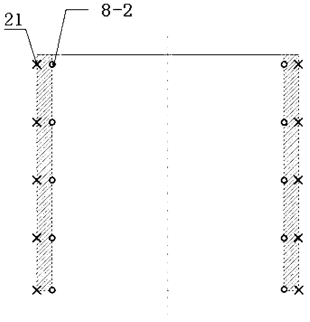
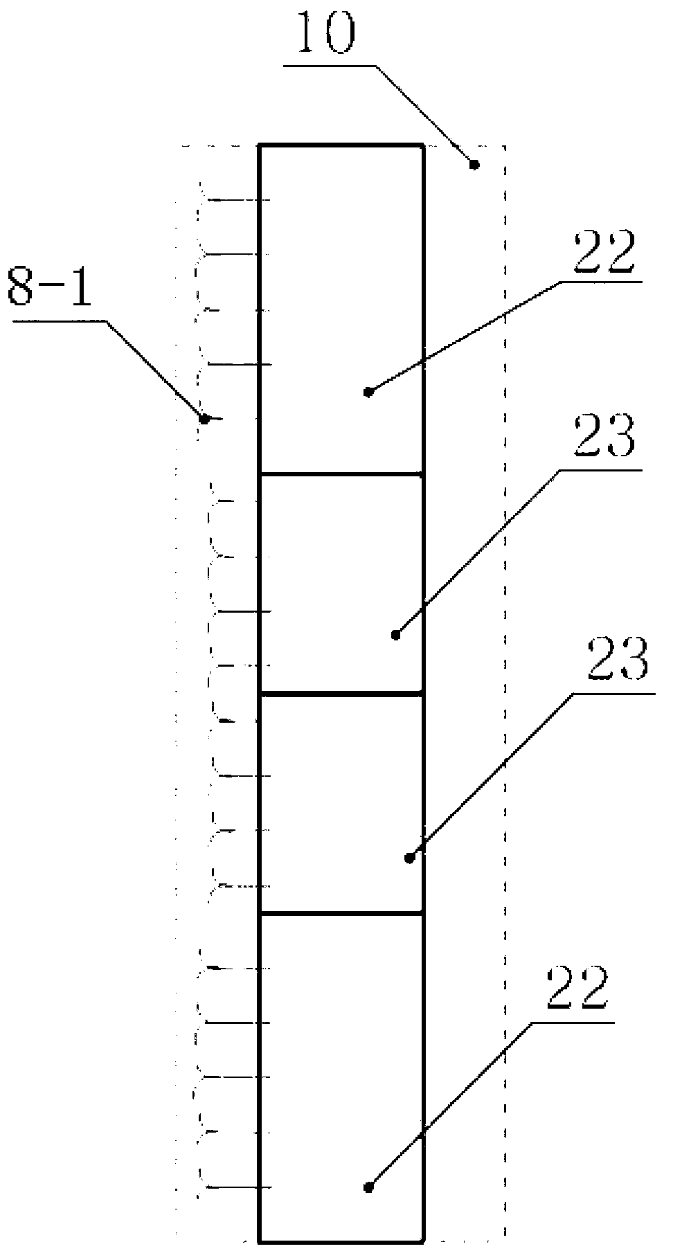
[0012] combine figure 1 , figure 2 and image 3 , a thermal conductivity and thermal contact resistance testing device, including a control system, a bracket 3, a first ball bushing 4-1, a second ball bushing 4-2, a sliding screw 5, an orientation steel ball and a pressure sensor 6, an auxiliary Heater 7, first temperature sensor 8-1, first temperature sensor 8-2, vacuum cover 9, test piece test area 10, stress loading device, vacuum exhaust port 13, water inlet and outlet 14, data acquisition system, sealed chassis 16, support plate 17, level adjustment rod 20, heating wire 21.

[0013] The stress loading device is composed of a hydraulic cylinder 11 and a pressure power source 12. The hydraulic cylinder 11 is located above the pressure power source 12; the data acquisition system is composed of a first temperature sensor 8-1 and a sealed data joint 15. ...


PUM


Abstract

The invention discloses a heat conduction coefficient and contact thermal resistance testing device. The testing device comprises a control system, a support 3, a first ball sleeve 4-1, a second ball sleeve 4-2, a sliding screw rod 5, an oriented steel ball and a pressure sensor 6, an auxiliary heater 7, a first temperature sensor 8-1, a second temperature sensor 8-2, a vacuum cap 9, a test piece test zone 10, a stress loading device, a vacuum drainage air port 13, water inlet and outlet ports 14, a data acquisition system, a sealing chassis 16, a mounting plate 17, a horizontal adjusting rod 20 and a heater strip 21, wherein a thermal flowmeter 22, the oriented steel ball and the pressure sensor 6, the support 3, the mounting plate 17 and heating refrigeration sleeves 1 are symmetrical in an up-down manner. According to the invention, the auxiliary heater which can reduce the axial heat loss is arranged along the y-direction, and a temperature gradient of a controllable temperature radiation shield simulation test region is arranged at the periphery of the test zone so as to reduce heat loss of a cross section direction.

Description

technical field [0001] The invention belongs to the field of measuring thermal conductivity and contact thermal resistance, and in particular relates to a device for accurately measuring material thermal conductivity and contact thermal resistance. Background technique [0002] The determination of thermal conductivity can be roughly divided into steady-state method and unsteady-state method. The so-called steady-state method is to measure a constant temperature difference of the substance to be measured, and then measure the heat flow formed under the given temperature difference, and the thermal conductivity of the substance can be obtained by Fourier's heat conduction law; the so-called unsteady-state method generally adopts A transient heat source is used for heating, and then the dynamic temperature response of the substance to be determined is measured, and the thermal conductivity of the substance is obtained by analyzing the relationship between the temperature chang...

Claims


Application Information

Patent Timeline
IPC IPC(8): G01N25/20
Inventor 宣益民张平李强徐德好
Owner NANJING UNIV OF SCI & TECH
Why Eureka
Try Eureka