Method for designing wireless power transmission device

A technology of wireless power transmission and design methods, applied in the direction of circuit devices, circuits, inductors, etc., can solve the problems of blind repetition, heavy workload, and low efficiency of impedance testing tests

Active Publication Date: 2013-07-17
INST OF ELECTRICAL ENG CHINESE ACAD OF SCI
View PDF3 Cites 21 Cited by
  • Summary
  • Abstract
  • Description
  • Claims
  • Application Information

AI Technical Summary

Problems solved by technology

[0004] The technical problem to be solved by the present invention is to provide an optimal design method of a wireless power transmission device to solve the problems of blind repetition, inefficiency, and heavy workload of compensation capacitance matching tests and impedance test tests in the current design process of wireless power transmission devices , to shorten the design cycle of wireless power transmission devices and save design costs

Method used


Image

  • Method for designing wireless power transmission device
  • Method for designing wireless power transmission device
  • Method for designing wireless power transmission device

Examples


Embodiment Construction

[0062] The present invention will be further described below in conjunction with the accompanying drawings and specific embodiments.

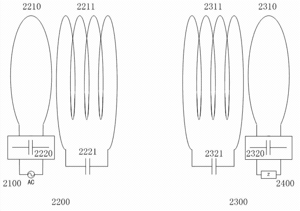
[0063] The structure of the wireless power transmission device applying the design method of the present invention is as follows: figure 2 As shown, it includes a high-frequency power supply 2100, a load 2400, a transmitting coil 2210, an amplifying coil at the transmitting end 2211, an amplifying coil at the receiving end 2311, a receiving coil 2310, a resonant compensation capacitor 2220 for the transmitting coil, a resonant compensation capacitor 2221 for the amplifying coil at the transmitting end, and a receiving coil. end amplifier coil resonance compensation capacitor 2321 and receiving coil resonance compensation capacitor 2320 . The transmitting coil and the amplifying coil at the transmitting end constitute the transmitting end 2200 ; the amplifying coil at the receiving end and the receiving coil constitute the receiving end 2300 . ...


PUM


Abstract

The invention discloses a method for designing a wireless power transmission device. The method comprises the following steps of: A, winding and installing a transmitting coil, a transmitting end amplifying coil, a receiving end amplifying coil and a receiving coil of the wireless power transmission device according to the design requirements and the given conditions; B, measuring electric parameters of the transmitting coil, the transmitting end amplifying coil, the receiving end amplifying coil and the receiving coil; C, establishing a multi-coil coupled wireless power transmission device system circuit model based on a mutual inductance model by using the actually measured electric parameters of the coils; D, setting an optimization object function and constraint conditions, and establishing a nonlinear programming model; E, solving a nonlinear programming problem to obtain a resonance compensation capacitance value; and F, configuring a capacitor according to the calculated resonance compensation capacitance value.

Description

technical field [0001] The invention relates to a design method of a wireless power transmission device, in particular to a method for designing multiple resonance compensation capacitors of a wireless power transmission device by combining circuit simulation and nonlinear programming theory. Background technique [0002] The application prospect of wireless power transmission technology is broad. Since the Massachusetts Institute of Technology (MIT) used magnetic coupling resonance wireless power transmission technology to light up a 60W light bulb at a distance of 2.16m in 2007, this technology has attracted more and more attention. Wireless power transmission schemes based on this technology have been proposed one after another. One of their common features is that each of the four coils is connected with a compensation resonant capacitor, and the four compensation capacitors have a great influence on the performance of the system. The two resonant coils often work at res...

Claims


Application Information

Patent Timeline
Patent Type & Authority Applications(China)
IPC IPC(8): H02J17/00H01F38/14H02J50/12H02J50/50
Inventor 廖承林朱庆伟王丽芳
Owner INST OF ELECTRICAL ENG CHINESE ACAD OF SCI
Why Eureka
Try Eureka