
Flow pipe for the turbulence generator of the headbox of a fibre web machine and a turbulence generator of the headbox of a fibre web machine
A fiber web machine and turbulence generator technology, which is applied in the field of turbulence generators, can solve the problems of large module size, difficult to change the turbulence generator, and the flow distribution cannot be changed in a small proportion, so as to reduce or increase the number of Effect
- Summary
- Abstract
- Description
- Claims
- Application Information
AI Technical Summary
Problems solved by technology
Method used
Image

Examples
Embodiment Construction
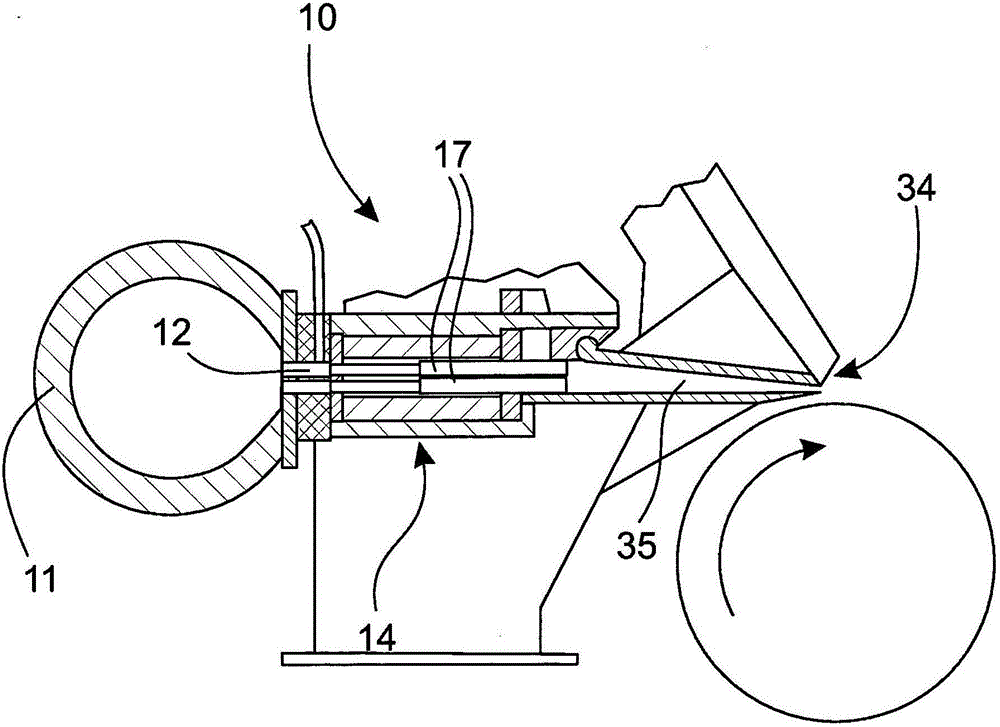
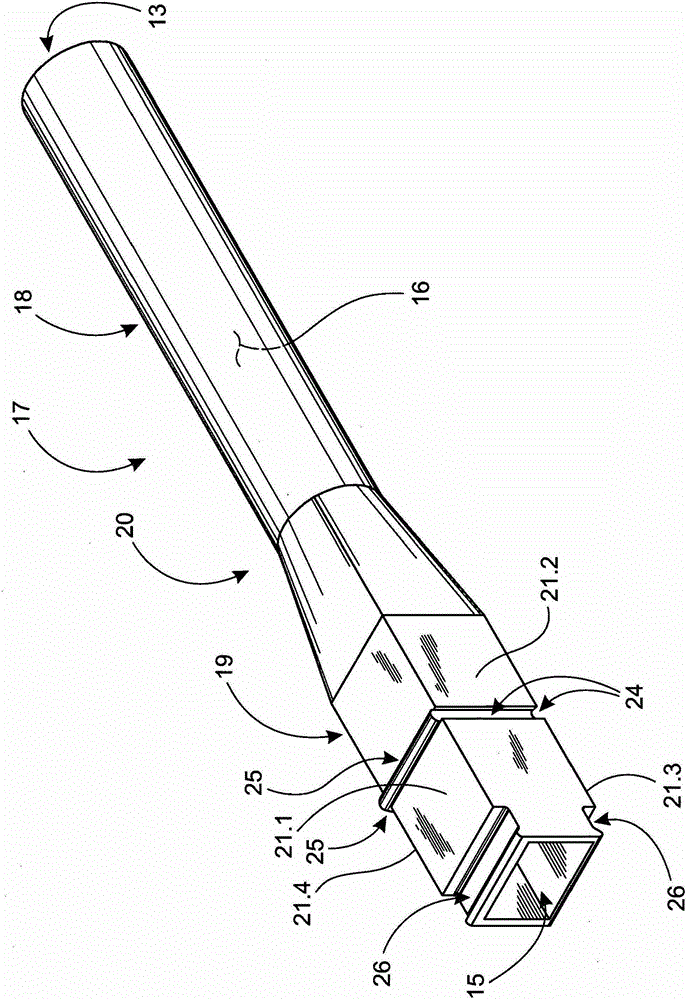
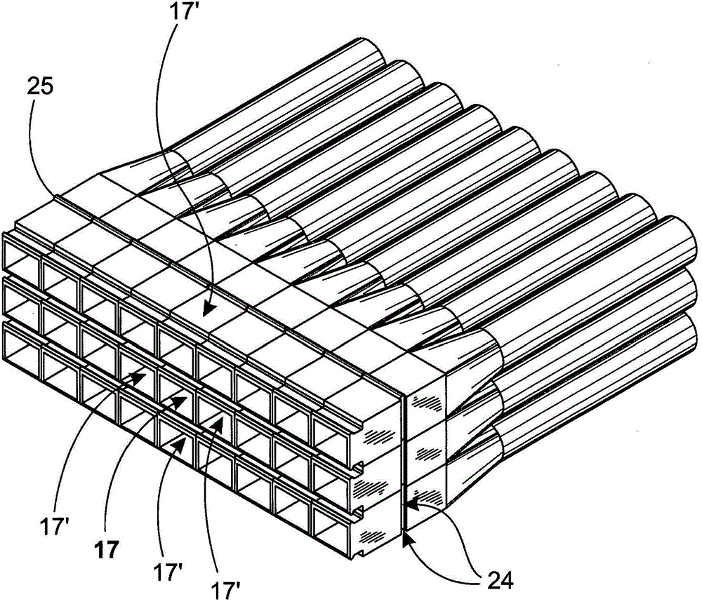
[0021] figure 1 A rough schematic sectional view of an example of a headbox 10 of a fiber web machine is shown viewed from the side. The fiber suspension is led in a manner known per se from the inlet header 11 of the headbox 10 through the manifold grooves 12 to a turbulence generator 14 consisting of several flow tubes 17 arranged in a row and overlapping each other. From the turbulence generator 14 the fiber suspension travels to a slice channel 35 and from there onwards over a schematically shown slice lip 34 to a forming wire (not shown in the figure). In addition, in the discharge opening 35 there may be a plurality of fins (not shown) immediately following the turbulence generator 14 . In the turbulence generator 14, the concentration distribution of the fiber suspension is uniform and any floes that may have formed in the fiber suspension are dispersed. Disperses flocs by creating shear and turbulence in the flow. The turbulence is sufficient to keep the fibers sepa...
PUM
 Abstract
Description
Claims
Application Information