Infrared signal processing circuit for reducing interference

An infrared signal and processing circuit technology, applied in electrical components, transmission systems, etc., can solve problems such as reducing the performance of 3D glasses, affecting the high-frequency performance of circuits, and 3D glasses flickering, so as to solve the problem of easy saturation and increase the radiation distance. , the effect of effective interference signal

Active Publication Date: 2015-10-28
GOERTEK INC
View PDF5 Cites 0 Cited by
  • Summary
  • Abstract
  • Description
  • Claims
  • Application Information

AI Technical Summary

Problems solved by technology

This infrared signal processing circuit is easy to enter saturation, which will affect the high-frequency infrared signal and affect the high-frequency performance of the circuit
[0004] With the development of 3D technology, infrared technology is also applied to 3D equipment, such as infrared 3D glasses, but, as figure 1 The application of the infrared signal processing circuit shown in the 3D glasses will cause the flickering phenomenon of the 3D glasses and reduce the performance of the 3D glasses

Method used


Image

  • Infrared signal processing circuit for reducing interference
  • Infrared signal processing circuit for reducing interference
  • Infrared signal processing circuit for reducing interference

Examples


Embodiment 1

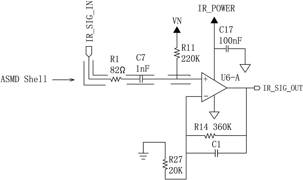
[0032] Such as figure 2As shown, an infrared signal processing circuit for reducing interference includes a first-stage amplifying circuit, the first-stage amplifying circuit includes an operational amplifier U6-A, and the non-inverting input terminal of the operational amplifier U6-A is electrically connected to a high-pass filter circuit, and the high-pass filter circuit includes The resistor R1 electrically connected to the infrared signal input terminal IR_SIG_IN, the resistance value of the resistor R1 is 82Ω, the resistor R1 is connected in series with the capacitor C7, the capacitance value of the capacitor C7 is 1nF, and the capacitor C7 is electrically connected to the non-inverting input terminal of the operational amplifier U6-A. The non-inverting input terminal of the operational amplifier U6-A is also electrically connected to a resistor R11, the resistance of the resistor R11 is 220KΩ, and the resistor R11 is electrically connected to a bias voltage VN. The outp...

Embodiment 2

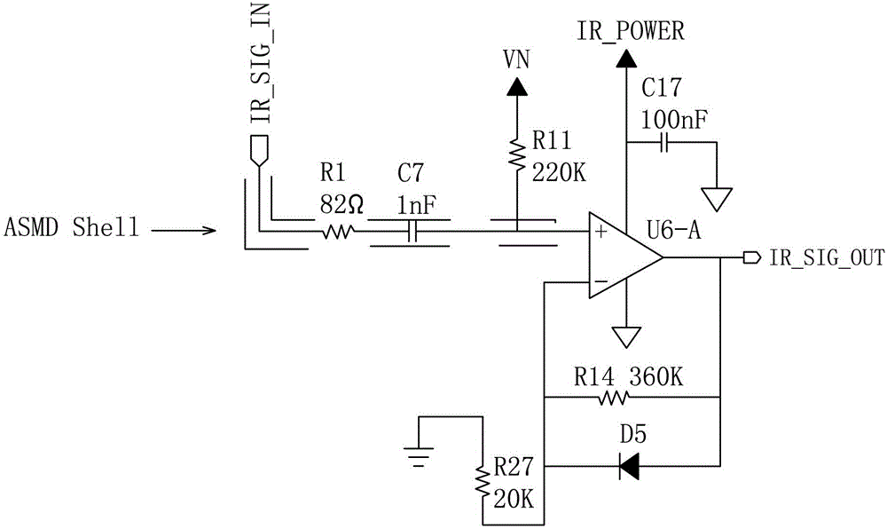
[0036] Such as image 3 As shown, this embodiment is basically the same as Embodiment 1, the difference is:

[0037] In this embodiment, a second-level buffer circuit and a third-level comparison circuit are added between the first-level amplification circuit and the infrared signal output terminal IR_SIG_OUT.

[0038] Such as image 3 As shown, the secondary buffer circuit includes a voltage follower U5-B, the non-inverting input terminal of the voltage follower U5-B is electrically connected to a capacitor C12, the capacitance value of the capacitor C12 is 100nF, the capacitor C12 is connected in series with a resistor R30, and the resistor R30 The resistance value is 82Ω, and the resistor R30 is electrically connected to the output terminal of the operational amplifier U6-A in the first-stage amplifying circuit. The non-inverting input terminal of the voltage follower U5-B is also electrically connected to a resistor R28, the resistance of the resistor R28 is 100KΩ, and t...

Embodiment 3

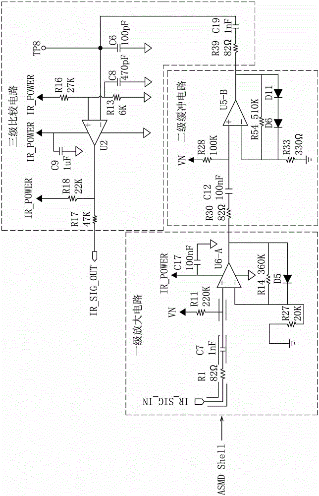
[0043] Such as Figure 4 As shown, this embodiment is basically the same as Embodiment 2, the difference is:

[0044] The secondary buffer circuit is electrically connected to the tertiary amplifying circuit, and the tertiary amplifying circuit is electrically connected to the infrared signal output terminal IR_SIG_OUT.

[0045] Such as Figure 4 As shown, the inverting input terminal of the operational amplifier U6-A in the primary amplifier circuit is electrically connected to a resistor R27 after being connected to the first voltage stabilization filter circuit, and the resistor R27 is electrically connected to the bias voltage VN.

[0046] Such as Figure 4 As shown, the inverting input terminal of the voltage follower U5-B in the secondary buffer circuit is electrically connected to a resistor R38 after the second voltage stabilization filter circuit is connected. The resistance value of the resistor R38 is 47KΩ, and the resistor R38 is electrically connected to a Resi...


PUM


Abstract

The invention discloses an infrared signal processing circuit capable of reducing disturbance and relates to the technical field of infrared signal circuits. The infrared signal processing circuit capable of reducing the disturbance comprises an operation amplifier U6-A, the non-inverting input end of the operation amplifier U6-A is electrically connected with an infrared signal input end IR_SIG_IN, and the output end of the operation amplifier U6-A is electrically connected with a first voltage stabilization filtering circuit. The first voltage stabilization filtering circuit comprises a resistor R14 with two ends electrically connected with the inverting input end and the output end of the operation amplifier U6-A. The first voltage stabilization filtering circuit further comprises a diode D5 with an anode electrically connected with the output end of the operation amplifier U6-A. A cathode of the diode D5 is electrically connected with the inverted input end of the operation amplifier U6-A. The output end of the operation amplifier U6-A is further electrically connected with an infrared signal output end IR_SIG_OUT. The infrared signal processing circuit effectively removes disturbance signals, increases a radiation distance of infrared signals and improves the radiation performance of the infrared signals.

Description

technical field [0001] The invention relates to the technical field of infrared signal circuits, in particular to an infrared signal processing circuit for reducing interference. Background technique [0002] Infrared is a wireless communication method that can transmit wireless data. Since the advent of infrared technology, it has been widely used, such as infrared devices such as infrared mouse, infrared printer and infrared keyboard. The infrared signal received by the infrared device needs to be amplified by the infrared signal processing circuit. However, in addition to the high-frequency infrared signal, the infrared signal received by the infrared device will also be mixed with some low-frequency interference signals, so these interference signals need to be filtered out. [0003] Those skilled in the art usually add a resistance-capacitance filter circuit in the infrared signal processing circuit to filter out low-frequency interference signals, such as figure 1 As...

Claims


Application Information

Patent Timeline
Patent Type & Authority Patents(China)
IPC IPC(8): H04B1/10
Inventor 李坡韩盈盈吴凡刘东宝孔晓丽
Owner GOERTEK INC
Why Eureka
Try Eureka