Infrared signal processing circuit capable of reducing disturbance
An infrared signal and processing circuit technology, applied in electrical components, transmission systems, etc., can solve problems such as reducing the performance of 3D glasses, affecting the high-frequency performance of circuits, and 3D glasses flickering, so as to solve the problem of easy saturation and increase the radiation distance. , the effect of effective interference signal
- Summary
- Abstract
- Description
- Claims
- Application Information
AI Technical Summary
Problems solved by technology
Method used
Image
Examples
Embodiment 1
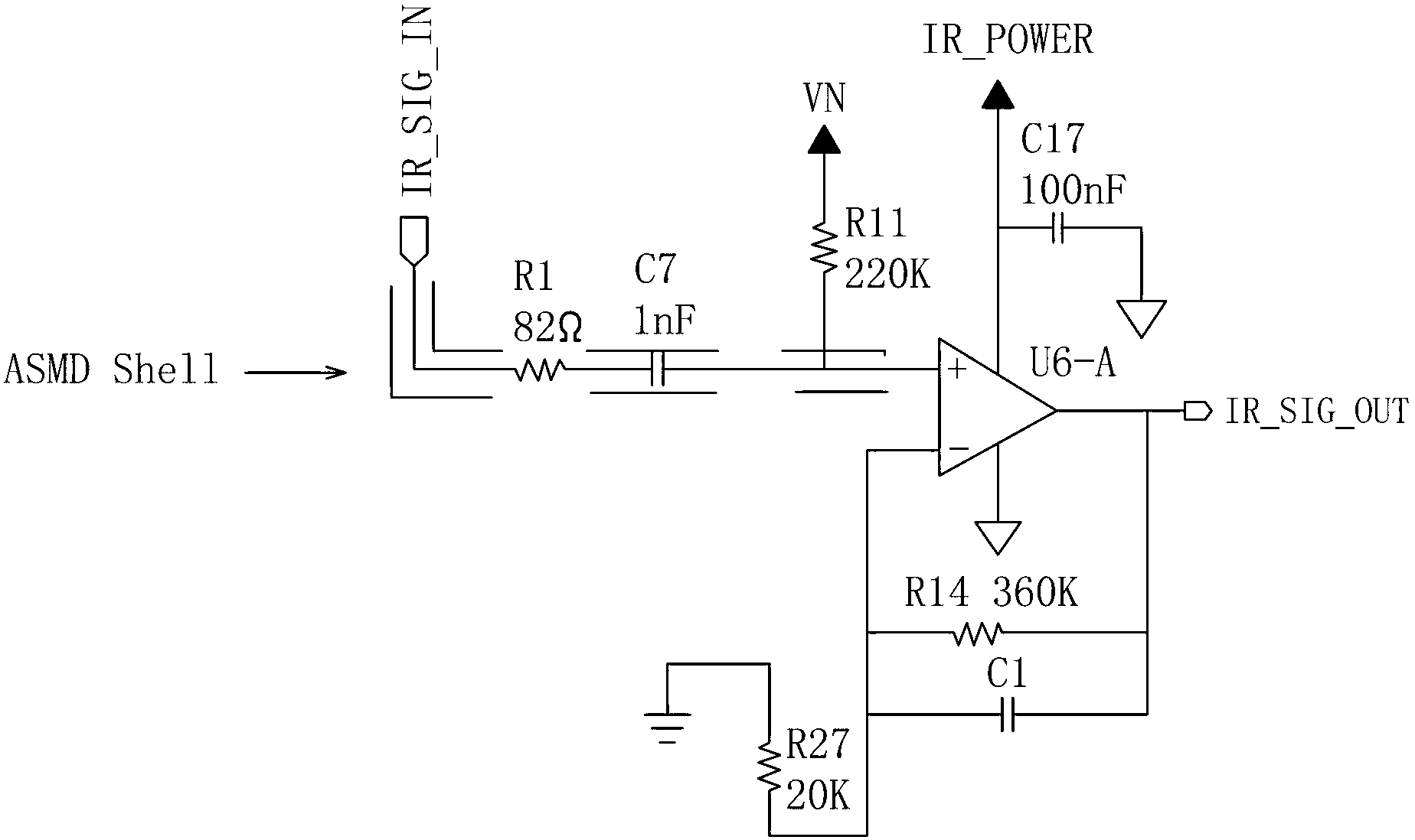
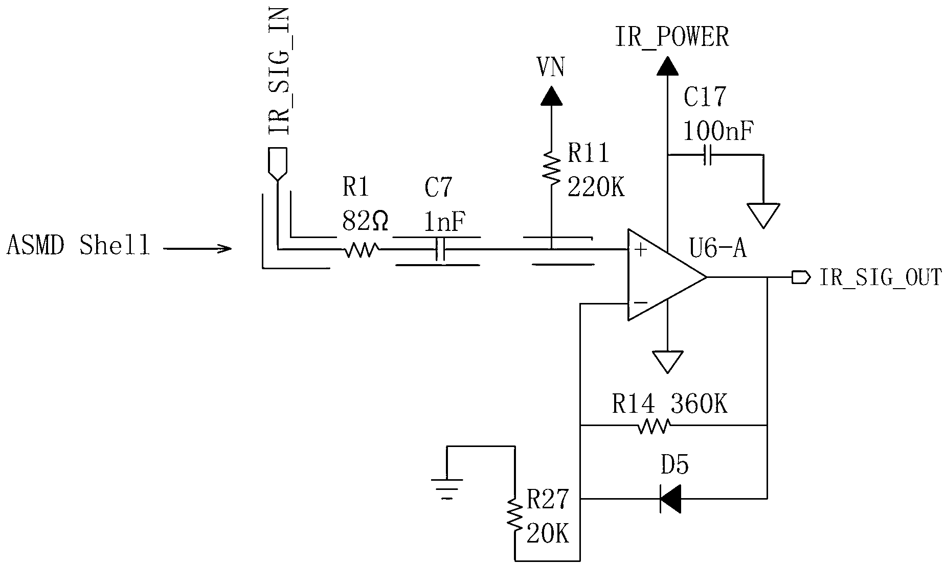
[0032] Such as figure 2As shown, an infrared signal processing circuit for reducing interference includes a first-stage amplifying circuit, the first-stage amplifying circuit includes an operational amplifier U6-A, and the non-inverting input terminal of the operational amplifier U6-A is electrically connected to a high-pass filter circuit, and the high-pass filter circuit includes The resistor R1 electrically connected to the infrared signal input terminal IR_SIG_IN, the resistance value of the resistor R1 is 82Ω, the resistor R1 is connected in series with the capacitor C7, the capacitance value of the capacitor C7 is 1nF, and the capacitor C7 is electrically connected to the non-inverting input terminal of the operational amplifier U6-A. The non-inverting input terminal of the operational amplifier U6-A is also electrically connected to a resistor R11, the resistance of the resistor R11 is 220KΩ, and the resistor R11 is electrically connected to a bias voltage VN. The outp...
Embodiment 2
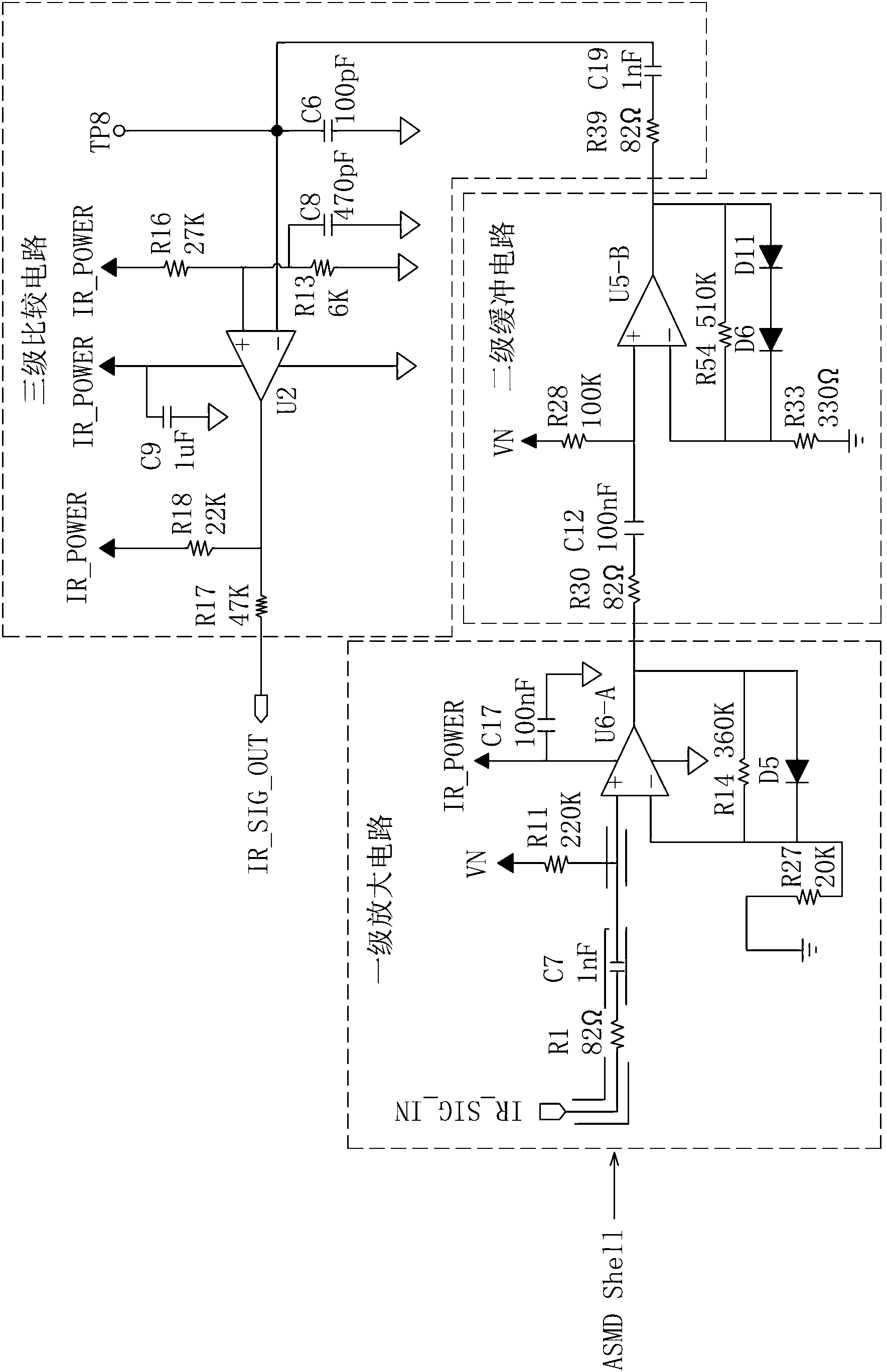
[0036] Such as image 3 As shown, this embodiment is basically the same as Embodiment 1, the difference is:
[0037] In this embodiment, a second-level buffer circuit and a third-level comparison circuit are added between the first-level amplification circuit and the infrared signal output terminal IR_SIG_OUT.
[0038] Such as image 3 As shown, the secondary buffer circuit includes a voltage follower U5-B, the non-inverting input terminal of the voltage follower U5-B is electrically connected to a capacitor C12, the capacitance value of the capacitor C12 is 100nF, the capacitor C12 is connected in series with a resistor R30, and the resistor R30 The resistance value is 82Ω, and the resistor R30 is electrically connected to the output terminal of the operational amplifier U6-A in the first-stage amplifying circuit. The non-inverting input terminal of the voltage follower U5-B is also electrically connected to a resistor R28, the resistance of the resistor R28 is 100KΩ, and t...
Embodiment 3
[0043] Such as Figure 4 As shown, this embodiment is basically the same as Embodiment 2, the difference is:
[0044] The secondary buffer circuit is electrically connected to the tertiary amplifying circuit, and the tertiary amplifying circuit is electrically connected to the infrared signal output terminal IR_SIG_OUT.
[0045] Such as Figure 4 As shown, the inverting input terminal of the operational amplifier U6-A in the primary amplifier circuit is electrically connected to a resistor R27 after being connected to the first voltage stabilization filter circuit, and the resistor R27 is electrically connected to the bias voltage VN.
[0046] Such as Figure 4 As shown, the inverting input terminal of the voltage follower U5-B in the secondary buffer circuit is electrically connected to a resistor R38 after the second voltage stabilization filter circuit is connected. The resistance value of the resistor R38 is 47KΩ, and the resistor R38 is electrically connected to a Resi...
PUM
 Abstract
Description
Claims
Application Information
 - R&D
- Intellectual Property
- Life Sciences
- Materials
- Tech Scout
- Unparalleled Data Quality
- Higher Quality Content
- 60% Fewer Hallucinations
Browse by: Latest US Patents, China's latest patents, Technical Efficacy Thesaurus, Application Domain, Technology Topic, Popular Technical Reports.
© 2025 PatSnap. All rights reserved.Legal|Privacy policy|Modern Slavery Act Transparency Statement|Sitemap|About US| Contact US: help@patsnap.com


