Ultra-thin telephone receiver

A receiver, ultra-thin technology, applied in the field of receivers, can solve the problem that the thickness cannot be installed with mobile phones, etc., achieve the effect of thickness reduction, front cavity space reduction, and enhanced high frequency effect

Active Publication Date: 2013-04-24
SUZHOU YICHUAN TECH CO LTD
View PDF4 Cites 23 Cited by
  • Summary
  • Abstract
  • Description
  • Claims
  • Application Information

AI Technical Summary

Problems solved by technology

[0005] In this way, a higher requirement is put forward for the volume of the receiver originally arranged between the frame and the screen, and the existing receiver is mainly composed of a driving mechanism, a casing, etc., and the driving mechanism includes an armature, an iron core, Coil, upper and lower magnets, diaphragm, diaphragm support, etc. Among them, the coil and iron core are arranged and sleeved on the armature to form a layer, and the upper and lower magnets are installed in the iron core. This layer is composed of the diaphragm and the diaphragm support. After one layer is superimposed, the driving mechanism is formed, and then the shell is installed on the outside of the driving mechanism. The thickness brought by such a structure obviously cannot be installed in such a narrow frame or close to "frameless" mobile phone.

Method used


Image

  • Ultra-thin telephone receiver
  • Ultra-thin telephone receiver
  • Ultra-thin telephone receiver

Examples


Embodiment 1

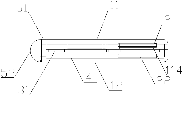
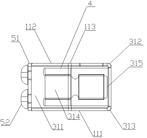
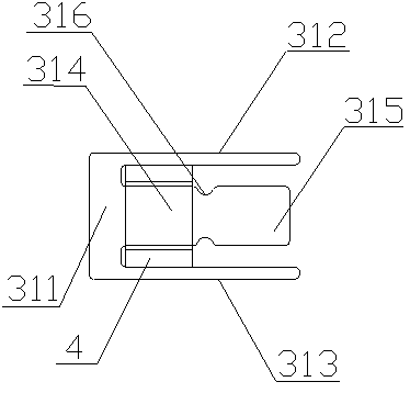
[0033] Such as Figure 1-6 As shown, the ultra-thin receiver in this embodiment includes a housing 1, a driving mechanism and a circuit board 51. The driving mechanism includes: an armature part 31, which is E-shaped, and the armature part 31 includes an integrally formed base part 311, Two side wing parts and a middle part, the two side wing parts are a first side wing part 312 and a second side wing part 313, the middle part includes a root part 314 located on the base part 311, and the root part 314 extends forward to form a diaphragm part 315; The coil part 4 is sleeved on the root part 314 in a gap, and it does not contact the root part 314. The coil part 4 has two starting lines and a termination line to be electrically connected to the positive and negative poles of the circuit board 51 respectively, that is, to connect On the welding platform 52, the armature part 31 can be made of soft magnetic alloy; the housing 1 includes: an upper housing 11, which is covered on th...

Embodiment 2

[0046] Others are the same as those described in Embodiment 1, except that the above-mentioned upper casing 11 and the lower casing 12 are fixedly connected, steps are provided around the inner side of the lower casing 12, the base 311, the first side wing The part 312 and the second side wing part 313 are fixedly connected on the step, and the fixed connection method can be welded, and a plurality of welding spots can be set on the above-mentioned positions for connection.

[0047] The working principle of the present invention is introduced below:

[0048] Both the original diaphragm and the armature part are combined into the current armature part 31, the root part 314 of the middle part of the armature part 31 is used for gap winding the coil 4, and the part extending forward of the root part 314 is used to replace the existing diaphragm Diaphragm part 315, so that the space occupied by the original diaphragm is firstly compressed; the original shell and the iron core for ...


PUM


Abstract

The invention discloses an ultra-thin telephone receiver. A driving mechanism of the ultra-thin telephone receiver comprises an armature section and a coil section, wherein the armature section is E-shaped and comprises a base portion, two wing portions and a middle portion, the base portion, the two wing portions and the middle portion are formed in an integrated mode, the middle portion comprises a root part located on the base portion, the root part extends forward to form a vibrating diaphragm part, and the coil section is arranged on the root part in a sleeved mode at intervals. A shell of the ultra-thin telephone receiver comprises an upper shell and a lower shell, wherein the upper shell is arranged at the top of the driving mechanism in a covered mode, and comprises a cover plate and cover edges which are formed by extending downward from the periphery of the cover plate, a first magnet is fixedly connected to the inner wall, covered at the top of the vibrating diaphragm part, of a section of the cover plate, the upper shell is made of magnetically soft alloy, the lower shell is arranged at the bottom of the driving mechanism in a covered mode relative to the upper shell, a second magnet is fixedly connected to the inner wall of the lower shell relative to the first magnet, the lower shell is made of magnetically soft alloy, and a sounding hole is formed in the upper shell or the lower shell. According to the ultra-thin telephone receiver, the thickness of an existing telephone receiver is reduced to the largest extent, and the ultra-thin telephone receiver is more suitable for the structure of a mobile phone with a narrow frame or a mobile phone which is nearly frameless.

Description

technical field [0001] The invention relates to a receiver, in particular to an ultra-thin receiver. Background technique [0002] The receiver, also known as the earpiece, is an electroacoustic device that converts audio electrical signals into sound signals without sound leakage. It is widely used in communication terminal equipment such as mobile phones, fixed phones, and earphones to realize audio, such as voice and music. etc. output. [0003] And along with the rapid development of mobile phone technology, higher technical requirements are also proposed for receivers for mobile phones. Entering the 21st century, especially in recent years, mobile phones have entered the era of smart phones. All the controls of the smart phone are done through the screen, and the touch operation has replaced the operation of the traditional physical buttons. Therefore, correspondingly, the requirements for the screen are getting higher and higher. [0004] In order to enable users to...

Claims


Application Information

Patent Timeline
Patent Type & Authority Applications(China)
IPC IPC(8): H04R1/10
CPCH04R31/006H04R9/10
Inventor 李梁周巍
Owner SUZHOU YICHUAN TECH CO LTD
Why Eureka
Try Eureka