Voltage source converter for high voltage direct current power transmission

a technology of voltage source converter and high voltage direct current, which is applied in the direction of power conversion system, electric power transfer ac network, electrical apparatus, etc., can solve the problems of increasing costs and further cost factors, and achieve the effect of reducing costs

Inactive Publication Date: 2013-01-01
ABB POWER GRIDS SWITZERLAND AG
View PDF14 Cites 23 Cited by
  • Summary
  • Abstract
  • Description
  • Claims
  • Application Information

AI Technical Summary

Benefits of technology

[0009]It is an object of the present invention to provide a high voltage AC / DC or DC / AC power conversion system according to the preamble of claim 1 which reduces the costs compared to the system described above.

Problems solved by technology

The disadvantage which such a configuration is that in case of n series-connected bridges also n converter reactors and n harmonic filters are needed which increases the costs considerably.
This results in the necessity to design the transformers 26 for DC, i.e. no standard transformers can be used, which constitutes a further cost factor.

Method used


Image

  • Voltage source converter for high voltage direct current power transmission
  • Voltage source converter for high voltage direct current power transmission
  • Voltage source converter for high voltage direct current power transmission

Examples


first embodiment

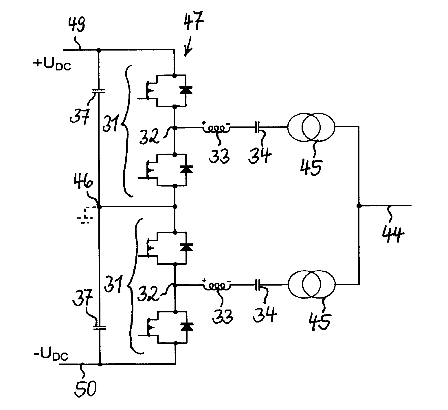
[0025]FIG. 5 shows a power conversion system with a multi-level

[0026]VSC, in this case a VSC 47 with two series-connected converter valve bridges 31, where the system represents a considerable improvement compared to the system of FIG. 4. The major difference between the two systems lies in that the system of FIG. 5 comprises a capacitor 34 in series with each of the converter reactors 33. The capacitors 34 block the DC voltages which occur at the AC phase terminals 32 of the bridges 31 from passing to the transformers 45, so that standard transformers can be used. Zero DC voltage can be measured again at the midpoint 46 between the two bridges 31, and it is again possible to connect midpoint 46 directly to ground. Alternatively, it is also possible to operate VSC 47 in a way where one of the poles 49 or 50 is connected to ground and the other to a positive or negative DC voltage. This would result in different DC voltage levels on the AC phase terminals 32 than in the embodiment of...

second embodiment

[0027]In a power conversion system with a multi-level VSC 47 and series capacitors 34, according to FIG. 6, a shunt-connected harmonic filter 35 is introduced. Due to the presence of the series capacitors 34, it is sufficient to have just one harmonic filter 35 to filter out the remaining high frequency components. The possible combination of the harmonic filters into just one filter results directly in the combination of the transformer 45 into one transformer 36. As is seen in FIG. 6, this reduction in components leads to a configuration, where the two series connections of converter reactor 33 and capacitor 34 are connected in parallel with each other and where the one transformer 36 and the one shunt-connect harmonic filter 35 are directly coupled to the common connection point 40 of the series connections. FIG. 6 shows additionally two surge arresters 43, each connected across one of the capacitors 34, which protect the capacitors 34 against overvoltage.

third embodiment

[0028]a power conversion system with a multi-level VSC 48 and series capacitors 34 is shown in FIG. 7. The VSC 48 comprises four series-connected converter valve bridges 31. All components which were already introduced with respect to FIG. 5 or 6 are marked with the same reference numbers. One series connection of converter reactor 33 and capacitor 34 is again connected to each of the AC phase terminals of the four bridges. The four series connections are all connected in parallel with each other and one harmonic filter 35 and one transformer 36 are coupled to the common connection point 41 via an additional reactor 38. The additional reactor 38 allows the reduction of converter reactors 33 in size, which results in a further cost reduction, especially with an increasing number of series connected bridges 31.


PUM


Abstract

A high voltage AC/DC or DC/AC power conversion system including a voltage source converter with at least two series-connected converter valve bridges, at least two reactors, where each of the reactors is connected to one of the AC phase terminals of the at least two bridges and at least one transformer connected to an AC supply voltage. In order to block a DC voltage from the at least one transformer, one of at least two capacitors is connected in series with each of the at least two reactors and is connected between the corresponding reactor and the at least one transformer.

Description

CROSS-REFERENCE TO RELATED APPLICATIONS[0001]This application is the national phase under 35 U.S.C. §371 of PCT / EP2007 / 059293 filed 5 Sep. 2007.FIELD OF THE INVENTION[0002]The invention relates to a high voltage AC / DC or DC / AC power conversion system comprising a voltage source converter with at least two series-connected converter valve bridges and at least two reactors, where each of the reactors is connected to one of the AC phase terminals of the at least two bridges.BACKGROUND OF THE INVENTION[0003]In high voltage direct current (HVDC) power transmission systems, two basic power converter technologies are used to transform the voltage from AC to DC and vice-versa. One converter technology or type is the line-commutated current source converter (CSC) and the other technology is the force-commutated or self-commutated voltage source converter (VSC). An overview of today's HVDC systems including the two technologies as well as their applications is for example given in “The ABC of...

Claims


Application Information

Patent Timeline
Patent Type & Authority Patents(United States)
IPC IPC(8): H02M7/5387H02M7/10
CPCH02J3/36H02M7/797Y02E60/60H02M7/05
Inventor ASPLUND, GUNNARJUHLIN, LARS-ERIK
Owner ABB POWER GRIDS SWITZERLAND AG
Why Eureka
Try Eureka